Toyota Venza: Installation
INSTALLATION
PROCEDURE
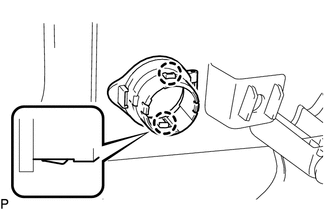
1. INSTALL REAR POWER POINT SOCKET COVER
|
(a) Engage the 2 claws to install the rear power point socket cover. |
|
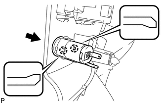
2. INSTALL REAR POWER POINT SOCKET ASSEMBLY
|
(a) Engage the 2 claws to install the rear power point socket assembly as shown in the illustration. |
|
3. INSTALL DECK TRIM SIDE PANEL ASSEMBLY RH
.gif)
4. CONNECT REAR SEAT OUTER BELT ASSEMBLY RH
HINT:
Use the same procedure for the RH side and the LH side (See page
).
5. INSTALL LUGGAGE HOLD BELT STRIKER ASSEMBLY
HINT:
Use the same procedure for the RH side and the LH side (See page
).
6. INSTALL RECLINING REMOTE CONTROL BEZEL RH
HINT:
Use the same procedure for the RH side and the LH side (See page
).
7. INSTALL REAR SEAT ASSEMBLY RH
8. CONNECT REAR SEAT RECLINING CONTROL CABLE
9. INSTALL REAR SEAT OUTER TRACK BRACKET COVER
10. INSTALL REAR SEAT INNER TRACK BRACKET COVER
11. INSTALL REAR SEAT CENTER HEADREST ASSEMBLY
12. INSTALL REAR SEAT HEADREST ASSEMBLY
13. INSTALL REAR FLOOR FINISH PLATE
14. INSTALL REAR SEAT SUB FLOOR PANEL ASSEMBLY
15. INSTALL NO. 1 DECK BOARD
16. INSTALL DECK SIDE TRIM BOX RH
17. INSTALL NO. 2 DECK BOARD SUB-ASSEMBLY
18. INSTALL DECK SIDE TRIM BOX LH
19. INSTALL NO. 3 DECK BOARD SUB-ASSEMBLY
20. INSTALL DECK BOARD ASSEMBLY
21. INSTALL TONNEAU COVER ASSEMBLY (w/ Tonneau Cover)
22. INSTALL REAR DOOR OPENING TRIM WEATHERSTRIP RH
HINT:
Use the same procedure for the RH side and the LH side (See page
).
23. INSTALL REAR DOOR SCUFF PLATE RH
HINT:
Use the same procedure for the RH side and the LH side (See page
).
 Components
COMPONENTS
ILLUSTRATION
ILLUSTRATION
ILLUSTRATION
ILLUSTRATION
...
 Removal
REMOVAL
PROCEDURE
1. REMOVE REAR DOOR SCUFF PLATE RH
HINT:
Use the same procedure for the RH side and the LH side (See page
).
2. REMOVE REAR DOOR OPENING TRIM WEATHERSTRIP RH
HINT:
Use the s ...
Other materials about Toyota Venza:
Cellular Phone Inspection
PROCEDURE
1.
CHECK USAGE CONDITION
(a) Check that the vehicle and cellular phone meet the following conditions:
NOTICE:
If changing cellular phone settings, updating software, etc. is necessary, make
sure to obtain the per ...
Inspection
INSPECTION
PROCEDURE
1. INSPECT CHARCOAL CANISTER ASSEMBLY
(a) Visually check the charcoal canister assembly.
(1) Visually check the charcoal canister assembly for cracks or damage.
If cracks or damage are found, replace the charcoal canister ...
Dtc Check / Clear
DTC CHECK / CLEAR
1. CHECK DTC (When Using Techstream)
(a) Check the DTCs.
(1) Connect the Techstream to the DLC3.
(2) Turn the ignition switch to ON.
(3) Turn the Techstream on.
(4) Read the DTCs following the prompts on the Techstream screen. Enter the ...

0.131