Toyota Venza: Components
COMPONENTS
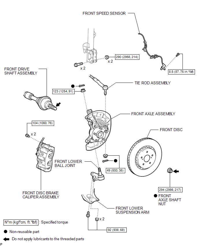
ILLUSTRATION

 Inspection
INSPECTION
PROCEDURE
1. INSPECT FRONT LOWER BALL JOINT
(a) Inspect the turning torque of the ball joint.
(1) Secure the front lower ball joint in a vise using aluminum plates.
(2) ...
Other materials about Toyota Venza:
Installation
INSTALLATION
PROCEDURE
1. INSTALL FRONT NO. 3 SPEAKER ASSEMBLY (for 13 Speakers)
(a) Engage the 3 claws to install the front No. 3 speaker assembly.
2. INSTALL FRONT PILLAR GARNISH CORNER PIECE (for ...
Removal
REMOVAL
PROCEDURE
1. DISCONNECT FRONT DOOR OPENING TRIM WEATHERSTRIP
2. REMOVE FRONT PILLAR GARNISH
3. REMOVE NO. 2 INSTRUMENT PANEL SPEAKER PANEL SUB-ASSEMBLY
4. REMOVE FRONT NO. 4 SPEAKER ASSEMBLY (for 13 Speakers)
(a) Remove the 2 ...
Disassembly
DISASSEMBLY
PROCEDURE
1. REMOVE MAGNETIC CLUTCH ASSEMBLY
(a) Place the compressor and magnetic clutch in a vise.
(b) Using SST, hold the magnetic clutch hub.
SST: 09985-00270
(c) Remove the bolt, ...

0.1488