Toyota Venza: Inspection
INSPECTION
PROCEDURE
1. INSPECT FRONT LOWER BALL JOINT
|
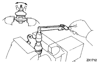
(a) Inspect the turning torque of the ball joint. (1) Secure the front lower ball joint in a vise using aluminum plates. (2) Install the nut to the front lower ball joint stud. (3) Using a torque wrench, turn the nut continuously at a rate of 3 to 5 seconds per turn and take the torque reading on the 5th turn. Turning torque: 0.7 to 4.5 N*m (7 to 46 kgf*cm, 6.2 to 40 in.*lbf) If the turning torque is not within the specified range, replace the front lower ball joint with a new one. |
|
(b) Inspect the dust cover.
(1) Check that the dust cover is not cracked and that there is no grease on it.
 Components
COMPONENTS
ILLUSTRATION
...
 Removal
REMOVAL
CAUTION / NOTICE / HINT
HINT:
Use the same procedure for the LH side and RH side.
The following procedure listed is for the LH side.
PROCEDURE
1. REMOVE FRONT WHEEL
2. ...
Other materials about Toyota Venza:
Communication Malfunction No. 1 (B2797)
DESCRIPTION
This DTC is stored when an error occurs in communication between the transponder
key amplifier and the transponder key ECU assembly.
HINT:
Some noise is found in the communication line.
DTC No.
DTC Detection Condition
...
Removal
REMOVAL
PROCEDURE
1. PRECAUTION
(See page )
2. ALIGN FRONT WHEELS FACING STRAIGHT AHEAD
3. DISCONNECT CABLE FROM NEGATIVE BATTERY TERMINAL
CAUTION:
Wait at least 90 seconds after disconnecting the cable from the negative (-)
battery terminal to disab ...
Terminals Of Ecu
TERMINALS OF ECU
1. TERMINALS OF ECU
Text in Illustration
*1
Component without harness connected
(Brake Actuator (Skid Control ECU))
Terminal No. (Symbol)
Terminal Description
1 (GND ...

0.1229