Toyota Venza: Disassembly
DISASSEMBLY
PROCEDURE
1. REMOVE MAGNETIC CLUTCH ASSEMBLY
|
(a) Place the compressor and magnetic clutch in a vise. |
|
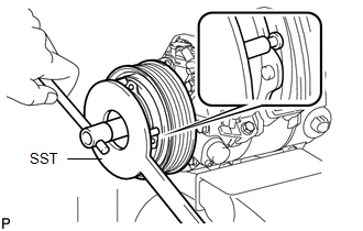
(b) Using SST, hold the magnetic clutch hub.
SST: 09985-00270
(c) Remove the bolt, magnetic clutch hub, and magnetic clutch washers.
HINT:
There is no set number of magnetic clutch washers because they are used for adjustment.
|
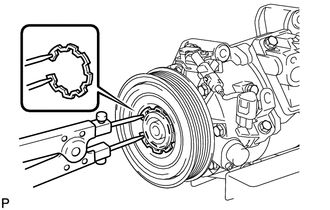
(d) Using a snap ring expander, remove the snap ring and then remove the magnetic clutch rotor. NOTICE: Take care not to damage the seal cover of the bearing when removing the snap ring. |
|
|
(e) Disconnect the connector. |
|
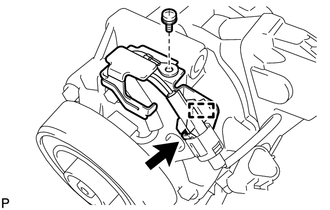
(f) Disengage the clamp.
(g) Remove the screw and the bracket.
|
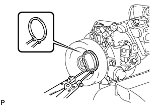
(h) Using a snap ring expander, remove the snap ring and magnetic clutch stator. NOTICE: Take care not to damage the seal cover of the bearing when removing the snap ring. |
|
 Removal
REMOVAL
PROCEDURE
1. RECOVER REFRIGERANT FROM REFRIGERATION SYSTEM
2. DISCONNECT CABLE FROM NEGATIVE BATTERY TERMINAL
NOTICE:
When disconnecting the cable, some systems need to be initialized ...
 Inspection
INSPECTION
PROCEDURE
1. INSPECT COMPRESSOR AND MAGNETIC CLUTCH (A/C LOCK SENSOR)
(a) Measure the resistance according to the value(s) in the table below.
Standard Resistance:
...
Other materials about Toyota Venza:
Problem Symptoms Table
PROBLEM SYMPTOMS TABLE
HINT:
Use the table below to help determine the cause of problem symptoms.
If multiple suspected areas are listed, the potential causes of the symptoms
are listed in order of probability in the "Suspected Area" ...
Speaker Circuit
DESCRIPTION
If there is a short in a speaker circuit, the radio and display receiver
assembly detects it and stops output to the speakers.
Thus sound cannot be heard from the speakers even if there is no malfunction
in the radio and display ...
Components
COMPONENTS
ILLUSTRATION
ILLUSTRATION
ILLUSTRATION
ILLUSTRATION
ILLUSTRATION
...

0.1769