Toyota Venza: Charge Warning Light Comes ON while Driving
PROCEDURE
|
1. |
CHECK LOCK FUNCTION OF CLUTCH PULLEY |
(a) Check the lock function with the pulley installed in the vehicle.
(1) Visually check that the rotor in the generator operates with the engine started.
(b) Check the lock function with the pulley removed from the vehicle.
(1) Remove the generator pulley cap.
|
(2) Hold the generator rotor using SST, and turn the clutch pulley clockwise
to check that the outer ring locks (See page
Text in Illustration
OK: The outer ring locks. |
|
.gif) ).
).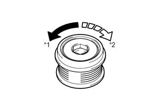
SST: 09820-63021
| NG | .gif) |
REPLACE CLUTCH PULLEY |
|
.gif)
|
2. |
CHECK LOCK OF CLUTCH PULLEY |
(a) Start the engine and visually check for looseness of the clutch pulley.
OK:
The clutch pulley is not loose.
| OK | |
REPLACE GENERATOR ASSEMBLY |
| NG | |
TIGHTEN CLUTCH PULLEY TO THE SPECIFIED TORQUE |
 Problem Symptoms Table
PROBLEM SYMPTOMS TABLE
Use the table below to help determine the cause of problem symptoms.
If multiple suspected areas are listed, the potential causes of the symptoms
are listed in o ...
 Noise Occurs from Generator while Engine is Running
PROCEDURE
1.
CHECK LOOSENESS OF V-RIBBED BELT
(a) Check the tension of the belt by pushing it down with a finger.
OK:
The tension of the belt is enough.
NG ...
Other materials about Toyota Venza:
Initialization
INITIALIZATION
1. RESET BACK DOOR CLOSE POSITION
NOTICE:
Perform initialization of the power back door system (power back door ECU initialization)
if one of the following is performed:
The cable is disconnected from the negative (-) battery termin ...
Diagnosis System
DIAGNOSIS SYSTEM
1. ECUS OR SENSORS WHICH COMMUNICATE THROUGH CAN COMMUNICATION SYSTEM
(a) CAN No. 1 Bus
(1) ECM
(2) Main body ECU (Driver side junction block)
(3) Combination meter
(4) Power steering ECU
(5) Air conditioning amplifier*3
(6) Center air ...
Vehicle Lift And Support Locations
VEHICLE LIFT AND SUPPORT LOCATIONS
1. NOTICE ABOUT VEHICLE CONDITION WHEN RAISING VEHICLE
(a) The vehicle must be unloaded before jacking up or raising the vehicle. Never
jack up or raise a heavily loaded vehicle.
(b) When removing any heavy components li ...

0.1599