Toyota Venza: Linear Solenoid Circuit (C1298/98)
DESCRIPTION
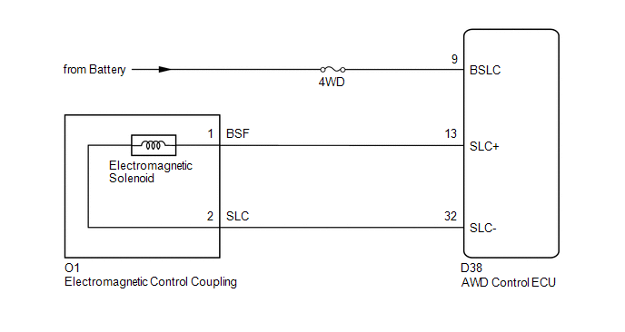
The AWD control ECU receives signals from each sensor to control clutch pressure to distribute torque according to the driving conditions.
|
DTC No. |
DTC Detection Condition |
Trouble Area |
|---|---|---|
|
C1298/98 |
When the following continues for 1 second or more: - With the current of the 0.8 A or more, an open or short in the electromagnetic solenoid circuit occurs. |
|
WIRING DIAGRAM
CAUTION / NOTICE / HINT
NOTICE:
Inspect the fuses for circuits related to this system before performing the following inspection procedure.
HINT:
Check the condition of each related circuit connector before troubleshooting
(See page .gif) ).
).
PROCEDURE
|
1. |
CHECK WIRE HARNESS (AWD CONTROL ECU - BATTERY) |
|
(a) Disconnect the ECU connector. |
|
(b) Measure the voltage of the wire harness side connector.
Standard Voltage:
|
Tester Connection |
Condition |
Specified Condition |
|---|---|---|
|
D38-9 (BSLC) - Body Ground |
Always |
11 to 14 V |
|
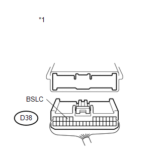
*1 |
Rear view of wire harness connector (to AWD Control ECU) |
| NG | .gif) |
REPAIR OR REPLACE HARNESS OR CONNECTOR |
|
.gif)
|
2. |
INSPECT ELECTRO MAGNETIC CONTROL COUPLING (ELECTROMAGNETIC SOLENOID) |
|
(a) Remove the coupling connector. |
|
(b) Measure the resistance of the solenoid.
Standard Resistance:
|
Tester Connection |
Condition |
Specified Condition |
|---|---|---|
|
1 (BSF) - 2 (SLC) |
Always |
2.2 to 2.6 Ω |
|
1 (BSF) - Body ground |
Always |
10 kΩ or higher |
|
2 (SLC) - Body ground |
Always |
10 kΩ or higher |
|
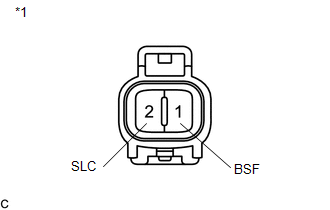
*1 |
Electromagnetic Solenoid |
| NG | |
REPLACE ELECTRO MAGNETIC CONTROL COUPLING |
|
|
3. |
CHECK WIRE HARNESS (ELECTROMAGNETIC CONTROL COUPLING - AWD CONTROL ECU) |
|
(a) Disconnect the ECU connector. |
|
(b) Measure the resistance of the wire harness side connector.
Standard Resistance:
|
Tester Connection |
Condition |
Specified Condition |
|---|---|---|
|
D38-13 (SLC+) - O1-1 (BSF) |
Always |
Below 1 Ω |
|
D38-32 (SLC-) - O1-2 (SLC) |
Always |
Below 1 Ω |
|
D38-13 (SLC+) - Body ground |
Always |
10 kΩ or higher |
|
D38-32 (SLC-) - Body ground |
Always |
10 kΩ or higher |
|
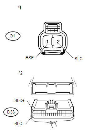
*1 |
Front view of wire harness connector (to Electromagnetic Solenoid) |
|
*2 |
Rear view of wire harness connector (to AWD Control ECU) |
| OK | |
REPLACE AWD CONTROL ECU |
| NG | |
REPAIR OR REPLACE HARNESS OR CONNECTOR |
 ABS Malfunction (C1296/96)
DESCRIPTION
If a malfunction in the speed sensor signal circuit occurs, the AWD control ECU
will output this DTC.
DTC No.
DTC Detecting Condition
Trouble Area
...
 Engine Circuit Malfunction (C1280/82)
DESCRIPTION
If a malfunction in the ECM circuit occurs, the AWD control ECU will output this
DTC.
DTC No.
DTC Detection Condition
Trouble Area
C12 ...
Other materials about Toyota Venza:
Installation
INSTALLATION
CAUTION / NOTICE / HINT
NOTICE:
When disconnecting the steering intermediate shaft assembly and pinion shaft
of steering gear assembly, be sure to place matchmarks before servicing.
PROCEDURE
1. INSTALL TIE ROD ASSEMBLY LH
(a) I ...
Inspection
INSPECTION
PROCEDURE
1. INSPECT BRAKE DISC INSIDE DIAMETER
(a) Using a brake drum gauge or an equivalent tool, measure the inside
diameter of the disc.
Standard inside diameter of a new disc:
190 mm (7.48 in.)
Maximum inside diamete ...
Rear Power Window LH does not Operate with Rear Power Window Switch LH
DESCRIPTION
When the engine is running or the ignition switch is ON, the power window regulator
motor assembly (for rear LH side) is operated by the power window regulator switch
assembly (for rear LH side). The power window regulator motor has motor, reg ...

0.1603