Toyota Venza: Front Sensor Communication Malfunction (C1AEC)
DESCRIPTION
This DTC is stored when there is an open or short circuit in the communication line between the front sensors and the ECU, or when there is a malfunction in a front sensor.
|
DTC No. |
DTC Detection Condition |
Trouble Area |
|---|---|---|
|
C1AEC |
An open or short circuit in the communication line between the front sensors and ECU or a malfunction in a front sensor during initialization mode after the engine switch is turned on (IG). |
|
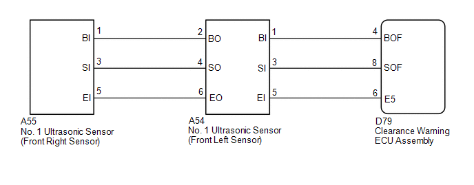
WIRING DIAGRAM
PROCEDURE
|
1. |
CHECK DTC OUTPUT (C1AEC) |
(a) Check for DTCs (See page .gif) ).
).
(b) Clear the DTCs (See page ).
(c) Recheck for DTCs (See page ).
|
Result |
Proceed to |
|---|---|
|
DTC C1AEC is output |
A |
|
No DTCs are output |
B |
| B | .gif) |
USE SIMULATION METHOD TO CHECK |
|
.gif)
|
2. |
CHECK HARNESS AND CONNECTOR (CLEARANCE WARNING ECU ASSEMBLY - FRONT LEFT SENSOR) |
(a) Disconnect the D79 clearance warning ECU assembly connector.
(b) Disconnect the A54 No. 1 ultrasonic sensor connector.
(c) Measure the resistance according to the value(s) in the table below.
Standard Resistance:
|
Tester Connection |
Condition |
Specified Condition |
|---|---|---|
|
D79-4 (BOF) - A54-1 (BI) |
Always |
Below 1 Ω |
|
D79-8 (SOF) - A54-3 (SI) |
Always |
Below 1 Ω |
|
D79-6 (E5) - A54-5 (EI) |
Always |
Below 1 Ω |
|
D79-4 (BOF) - Body ground |
Always |
10 kΩ or higher |
|
D79-8 (SOF) - Body ground |
Always |
10 kΩ or higher |
|
D79-6 (E5) - Body ground |
Always |
10 kΩ or higher |
| NG | |
REPAIR OR REPLACE HARNESS OR CONNECTOR |
|
|
3. |
CHECK HARNESS AND CONNECTOR (FRONT LEFT SENSOR - FRONT RIGHT SENSOR) |
(a) Disconnect the A55 No. 1 ultrasonic sensor connector.
(b) Measure the resistance according to the value(s) in the table below.
Standard Resistance:
|
Tester Connection |
Condition |
Specified Condition |
|---|---|---|
|
A54-2 (BO) - A55-1 (BI) |
Always |
Below 1 Ω |
|
A54-4 (SO) - A55-3 (SI) |
Always |
Below 1 Ω |
|
A54-6 (EO) - A55-5 (EI) |
Always |
Below 1 Ω |
|
A54-2 (BO) - Body ground |
Always |
10 kΩ or higher |
|
A54-4 (SO) - Body ground |
Always |
10 kΩ or higher |
|
A54-6 (EO) - Body ground |
Always |
10 kΩ or higher |
| NG | |
REPAIR OR REPLACE HARNESS OR CONNECTOR |
|
|
4. |
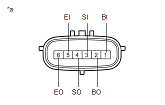
INSPECT NO. 1 ULTRASONIC SENSOR (FRONT LEFT SENSOR) |
|
(a) Measure the resistance according to the value(s) in the table below. Standard Resistance:
|
|
| NG | |
REPLACE NO. 1 ULTRASONIC SENSOR (FRONT LEFT SENSOR) |
|
|
5. |
REPLACE NO. 1 ULTRASONIC SENSOR (FRONT LEFT SENSOR) |
|
|
6. |
CHECK DTC OUTPUT (C1AEC) |
(a) Clear the DTCs (See page ).
(b) Check for DTCs (See page ).
|
Result |
Proceed to |
|---|---|
|
DTC C1AEC is output |
A |
|
No DTCs are output |
B |
| B | |
END |
|
|
7. |
REPLACE NO. 1 ULTRASONIC SENSOR (FRONT RIGHT SENSOR) |
|
|
8. |
CHECK DTC OUTPUT (C1AEC) |
(a) Clear the DTCs (See page ).
(b) Check for DTCs (See page ).
|
Result |
Proceed to |
|---|---|
|
DTC C1AEC is output |
A |
|
No DTCs are output |
B |
| A | |
REPLACE CLEARANCE WARNING ECU ASSEMBLY |
| B | |
END |
 Lost Communication with ECM / PCM "A" (U0100-U0142,U0155)
DESCRIPTION
These DTCs are stored when the clearance warning ECU assembly cannot receive
and recognize several signals via the CAN communication system.
DTC No.
DTC Detection ...
 Rear Sensor Communication Malfunction (C1AED)
DESCRIPTION
This DTC is stored when there is an open or short circuit in the communication
line between the rear sensors and the ECU, or when there is a malfunction in a rear
sensor.
...
Other materials about Toyota Venza:
Removal
REMOVAL
CAUTION / NOTICE / HINT
HINT:
Use the same procedure for the RH side and LH side.
The procedure listed below is for the LH side.
PROCEDURE
1. DISCONNECT CABLE FROM NEGATIVE BATTERY TERMINAL
CAUTION:
Wait at least 90 seconds aft ...
Transmission Fluid Temperature Sensor "A" Circuit Low Input (P0712,P0713)
DESCRIPTION
The Automatic Transmission Fluid (ATF) temperature sensor converts the fluid
temperature into a resistance value for use by the TCM.
The TCM applies a voltage to the temperature sensor through terminal THO1 of
the TCM.
The sensor resistanc ...
Removal
REMOVAL
PROCEDURE
1. DISCONNECT CABLE FROM NEGATIVE BATTERY TERMINAL
CAUTION:
Wait at least 90 seconds after disconnecting the cable from the negative (-)
battery terminal to disable the SRS system.
NOTICE:
When disconnecting the cable, some systems ne ...

0.1614