Toyota Venza: Vehicle Speed Sensor Malfunction (B2415)
DESCRIPTION
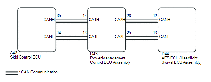
The AFS ECU (headlight swivel ECU assembly) receives signals indicating the front right wheel speed from the skid control ECU using CAN communication.
|
DTC No. |
DTC Detection Condition |
Trouble Area |
|---|---|---|
|
B2415 |
Malfunction in vehicle speed sensor |
|
WIRING DIAGRAM
CAUTION / NOTICE / HINT
NOTICE:
First perform the communication function inspections in How to Proceed with Troubleshooting to confirm that there are no CAN communication malfunctions before troubleshooting this symptom.
PROCEDURE
|
1. |
CHECK FOR DTC |
(a) Clear the DTCs (See page .gif) ).
).
(b) Check for DTCs (See page ).
OK:
DTC B2415 is not output.
| OK | .gif) |
USE SIMULATION METHOD TO CHECK |
|
.gif)
|
2. |
CHECK FOR DTC (ELECTRONICALLY CONTROLLED BRAKE SYSTEM) |
(a) Check for DTCs (See page ).
OK:
Electronically controlled brake system DTCs are not output.
| OK | |
REPLACE AFS ECU (HEADLIGHT SWIVEL ECU ASSEMBLY) |
| NG | |
GO TO ELECTRONICALLY CONTROLLED BRAKE SYSTEM |
 Height Control Sensor Malfunction (B2416)
DESCRIPTION
The DTC is stored when the headlight leveling ECU assembly detects malfunctions
in the rear height control sensor sub-assembly RH power source or rear height control
sensor sub-assemb ...
 Height Control Sensor Data Out of Range When Initializing (B2452)
DESCRIPTION
The headlight leveling ECU assembly stores this DTC if the sensor value received
from the height control sensor is out of range when performing initialization of
the headlight levelin ...
Other materials about Toyota Venza:
Brake Warning Light Remains ON
DESCRIPTION
The skid control ECU is connected to the combination meter via CAN communication.
If any of the following is detected, the brake warning light remains on:
The skid control ECU connector is disconnected from the skid control
ECU.
T ...
Removal
REMOVAL
PROCEDURE
1. DISCONNECT CABLE FROM NEGATIVE BATTERY TERMINAL
NOTICE:
When disconnecting the cable, some systems need to be initialized after the cable
is reconnected (See page ).
2. REMOVE FRONT WHEEL RH
3. REMOVE NO. 1 ENGINE UNDER COVER
4. ...
Removal
REMOVAL
PROCEDURE
1. PRECAUTION
CAUTION:
Be sure to read Precaution thoroughly before servicing (See page
).
2. DISCONNECT CABLE FROM NEGATIVE BATTERY TERMINAL
CAUTION:
Wait at least 90 seconds after disconnecting the cable from the negative (-)
bat ...

0.1638