Toyota Venza: Installation
INSTALLATION
CAUTION / NOTICE / HINT
HINT:
Perform "Inspection After Repair" after replacing the camshaft, No. 2 camshaft,
camshaft timing gear assembly or camshaft timing exhaust gear assembly (See page
.gif) ).
).
PROCEDURE
1. INSTALL NO. 2 CAMSHAFT BEARING
2. INSTALL NO. 1 CAMSHAFT BEARING
3. INSTALL OIL CONTROL VALVE FILTER
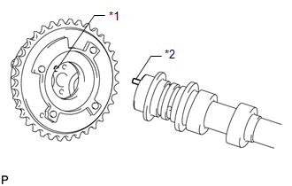
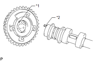
4. INSTALL CAMSHAFT TIMING EXHAUST GEAR ASSEMBLY
|
(a) Align and attach the knock pin of the No. 2 camshaft with the pin hole of the camshaft timing exhaust gear assembly. Text in Illustration
|
|
|
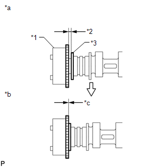
(b) Check that there is no clearance between the camshaft timing exhaust gear assembly and camshaft flange. Text in Illustration
|
|
|
(c) Fix the camshaft timing exhaust gear assembly with the bolt. Torque: 85 N·m {867 kgf·cm, 63 ft·lbf} NOTICE: Do not disassemble the camshaft timing exhaust gear. HINT: Perform "Inspection After Repair" after replacing the camshaft timing
exhaust gear assembly (See page |
|
.png)
5. SET NO. 1 CYLINDER TO TDC/COMPRESSION
|
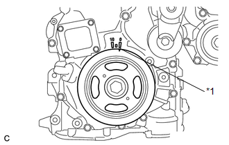
(a) Turn the crankshaft pulley until its timing notch (groove) and the timing mark "0" of the timing chain cover are aligned. Text in Illustration
|
|
6. INSTALL NO. 2 CAMSHAFT
|
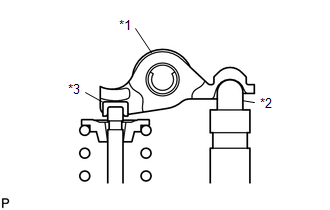
(a) Make sure that the valve rocker arms are installed as shown in the illustration. Text in Illustration
|
|
(b) Clean the camshaft journals.
(c) Apply a light coat of engine oil to the camshaft journals, camshaft housings and bearing caps.
|
(d) Hold up the chain and align the matchmark and the paint mark and install the camshaft. Text in Illustration
HINT: Perform "Inspection After Repair" after replacing the No. 2 camshaft
(See page |
|
7. INSTALL CAMSHAFT
|
(a) Make sure that the valve rocker arms are installed as shown in the illustration. Text in Illustration
|
|
(b) Clean the camshaft journals.
(c) Apply a light coat of engine oil to the camshaft journals, camshaft housings and bearing caps.
|
(d) Install the camshaft to the camshaft housing as shown in the illustration. Text in Illustration
HINT: Perform "Inspection After Repair" after replacing the camshaft (See page
|
|
8. INSTALL CAMSHAFT BEARING CAP
|
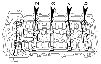
(a) Confirm the marks and numbers on the camshaft bearing caps and place them in their proper positions and directions. |
|
|
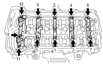
(b) Using several steps, uniformly tighten the 10 bolts in the sequence shown in the illustration. Torque: 27 N·m {275 kgf·cm, 20 ft·lbf} |
|

|
(c) Using several steps, uniformly tighten the 11 bolts in the sequence shown in the illustration. Torque: 16 N·m {163 kgf·cm, 12 ft·lbf} |
|
(d) Check the torque of each bolt again.
9. INSTALL CAMSHAFT TIMING GEAR ASSEMBLY
|
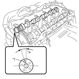
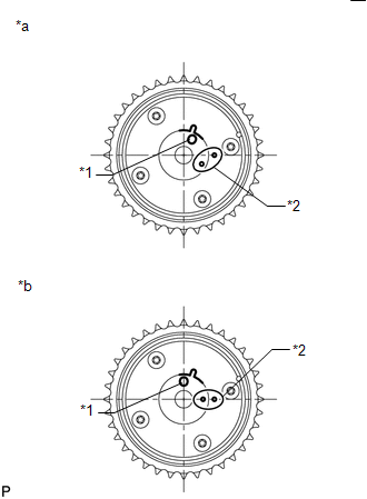
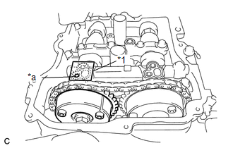
(a) Check the camshaft timing gear position. Text in Illustration
NOTICE:
|
|
|
(b) Install the camshaft timing gear as shown in the illustration. Text in Illustration
|
|
|
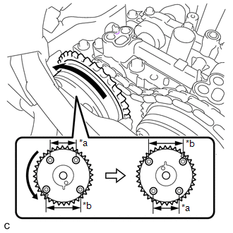
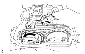
(c) Turn the camshaft timing gear approximately 180° counterclockwise. Text in Illustration
|
|
|
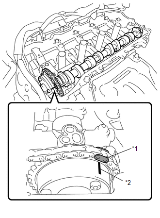
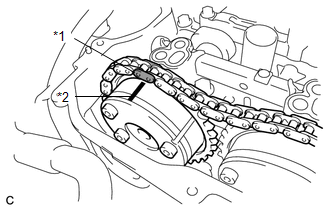
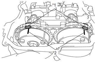
(d) Align the paint mark with the matchmark to install the chain. Text in Illustration
|
|
|
(e) Align and attach the knock pin of the No. 1 camshaft with the pin hole of the camshaft timing gear. Text in Illustration
|
|
|
(f) Check that there is no clearance between the camshaft timing gear and camshaft flange. Text in Illustration
|
|
(g) Secure the camshaft in place by hand, and then install the installation bolt of the camshaft timing gear by hand.
NOTICE:
Do not use any tools to install the bolt. If the bolt is installed using a tool, the lock pin will be damaged.
(h) If the lock pin has not been released, release it.
|
(1) After cleaning and degreasing the intake side VVT oil hole on the No. 1 camshaft bearing cap, completely seal the oil hole with adhesive tape or equivalent as shown in the illustration to prevent air from leaking. Text in Illustration
NOTICE: Be sure to seal the oil hole completely because air leaks due to insufficient sealing will prevent the lock pin from being released. |
|
(2) Make a hole in the adhesive tape covering the oil hole as shown in the illustration. (Procedure A)
|
(3) Apply approximately 200 kPa (2.0 kgf/ cm2, 29 psi) of air pressure to the hole made in procedure A to release the lock pin. NOTICE:
|
|
(4) Forcibly turn the camshaft timing gear in the advance direction (counterclockwise).
HINT:
Depending on the air pressure applied, the camshaft timing gear may turn in the advance direction without assistance by hand.
(5) Remove the adhesive tape from the No. 1 camshaft bearing cap.
|
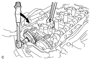
(i) Using a wrench to hold the hexagonal portion of the No. 1 camshaft, install the bolt. Torque: 85 N·m {867 kgf·cm, 63 ft·lbf} NOTICE: Be careful not to damage the cylinder head or spark plug tube with the wrench. |
|
|
(j) Check that each matchmark of the camshaft timing gear and camshaft timing exhaust gear are aligned with each matchmark located as shown in the illustration. Text in Illustration
HINT: Perform "Inspection After Repair" after replacing the camshaft timing
gear assembly (See page |
|
10. ADD ENGINE OIL
11. INSTALL TIMING CHAIN GUIDE
12. INSTALL NO. 1 CHAIN TENSIONER ASSEMBLY
|
(a) Turn the crankshaft approximately 10° clockwise. |
|
.png)
|
(b) Install a new gasket and the chain tensioner with the 2 bolts. Torque: 10 N·m {102 kgf·cm, 7 ft·lbf} NOTICE: Make sure not to drop the gasket inside the timing chain cover. |
|
.png)
(c) Remove the pin from the stopper plate.
13. CHECK NO. 1 CYLINDER TO TDC/COMPRESSION
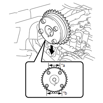
(a) Turn the crankshaft pulley until its timing notch (groove) and the timing mark "0" of the timing chain cover are aligned.
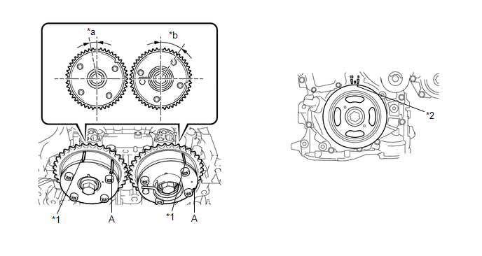 Text in Illustration
|
*1 |
Timing Mark |
|
*2 |
Timing Notch |
|
*a |
Approximately 7° |
|
*b |
Approximately 32° |
(b) Check that the timing marks of the camshaft timing gears are as shown in the illustration. If not, turn the crankshaft 1 revolution (360°) to align the timing marks as shown in the illustration.
HINT:
"A" is not a timing mark.
14. INSTALL TIMING CHAIN COVER PLATE
|
(a) Install a new gasket and the timing chain cover plate with the 4 bolts. Torque: 10 N·m {102 kgf·cm, 7 ft·lbf} |
|
.png)
15. INSTALL TIMING CHAIN COVER TIGHT PLUG
16. INSTALL CYLINDER HEAD COVER SUB-ASSEMBLY
17. INSTALL IGNITION COIL ASSEMBLY
18. CONNECT ENGINE WIRE
|
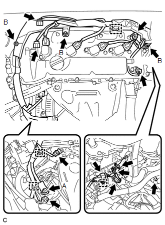
(a) Connect the connectors and clamps, and install the engine wire to the engine with the bolts and nuts. Torque: Nut A : 9.8 N·m {100 kgf·cm, 87 in·lbf} Nut B : 8.4 N·m {86 kgf·cm, 74 in·lbf} Bolt : 8.4 N·m {86 kgf·cm, 74 in·lbf} |
|
19. CONNECT VENTILATION HOSE ASSEMBLY
|
(a) Connect the ventilation hose to the cylinder head cover. |
|
.png)
20. INSTALL ENGINE MOVING CONTROL ROD
21. INSTALL AIR CLEANER CASE SUB-ASSEMBLY
22. INSTALL AIR CLEANER FILTER ELEMENT SUB-ASSEMBLY
23. INSTALL AIR CLEANER CAP SUB-ASSEMBLY
|
(a) Install the air cleaner cap sub-assembly with the 2 bolts. Torque: 5.0 N·m {51 kgf·cm, 44 in·lbf} |
|
.png)
|
(b) Connect the air cleaner hose and tighten the hose clamp bolt. |
|
.png)
(c) Connect the mass air flow meter connector and install the wire harness clamp to the air cleaner cap.
24. INSTALL INLET AIR CLEANER ASSEMBLY
25. CONNECT CABLE TO NEGATIVE BATTERY TERMINAL
NOTICE:
When disconnecting the cable, some systems need to be initialized after the cable
is reconnected (See page ).
26. INSPECT FOR OIL LEAK
27. INSTALL FRONT FENDER APRON SEAL RH
28. INSTALL FRONT FENDER LINER RH
29. INSTALL NO. 1 ENGINE UNDER COVER
30. INSTALL NO. 1 ENGINE COVER SUB-ASSEMBLY
31. INSTALL FRONT WHEEL RH
 Removal
REMOVAL
PROCEDURE
1. DISCONNECT CABLE FROM NEGATIVE BATTERY TERMINAL
NOTICE:
When disconnecting the cable, some systems need to be initialized after the cable
is reconnected (See page ).
2. RE ...
 Cylinder Block
...
Other materials about Toyota Venza:
Door Control Switch
Components
COMPONENTS
ILLUSTRATION
Inspection
INSPECTION
PROCEDURE
1. INSPECT DOOR CONTROL SWITCH ASSEMBLY
(a) Measure the resistance according to the value(s) in the table below.
Standard Resistance:
Tester Conn ...
Removal
REMOVAL
CAUTION / NOTICE / HINT
HINT:
Use the same procedure for the LH side and RH side.
The following procedure listed below is for the LH side.
PROCEDURE
1. REMOVE REAR WHEEL
2. SEPARATE REAR SPEED SENSOR
3. REMOVE REAR AXLE SHAF ...
Brake Signal Malfunction (B2284)
DESCRIPTION
The power management control ECU receives brake signal information from 2 sources.
It receives a signal from the stop light switch assembly via a direct line, and
a signal from the ECM via CAN. If the information from these 2 sources is incons ...

0.1363