Toyota Venza: ECM Power Source Circuit
DESCRIPTION
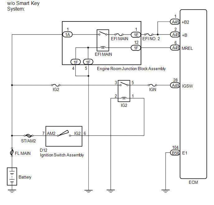
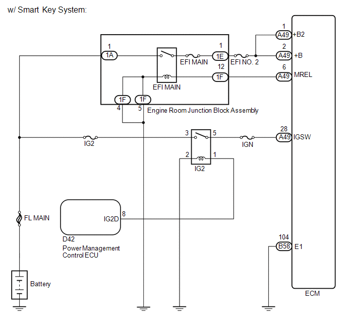
When the ignition switch is turned to ON, the battery voltage is applied to IGSW of the ECM. The output signal from the MREL terminal of the ECM causes a current to flow to the coil, closing the contact of the engine room junction block assembly (EFI MAIN relay) and supplying power to terminals +B and +B2 of the ECM.
WIRING DIAGRAM
CAUTION / NOTICE / HINT
NOTICE:
Inspect the fuses for circuits related to this system before performing the following inspection procedure.
PROCEDURE
|
1. |
CHECK HARNESS AND CONNECTOR (ECM - BODY GROUND) |
(a) Disconnect the ECM connector.
(b) Measure the resistance according to the value(s) in the table below.
Standard Resistance (Check for Open):
|
Tester Connection |
Condition |
Specified Condition |
|---|---|---|
|
B58-104 (E1) - Body ground |
Always |
Below 1 Ω |
| NG | .gif) |
REPAIR OR REPLACE HARNESS OR CONNECTOR (ECM - BODY GROUND) |
|
.gif)
|
2. |
INSPECT ECM (IGSW VOLTAGE) |
|
(a) Disconnect the ECM connector. |
|
(b) Turn the ignition switch to ON.
(c) Measure the voltage according to the value(s) in the table below.
Standard Voltage:
|
Tester Connection |
Switch Condition |
Specified Condition |
|---|---|---|
|
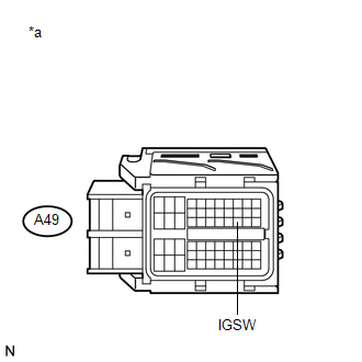
A49-28 (IGSW) - Body ground |
Ignition switch ON |
11 to 14 V |
|
*a |
Front view of wire harness connector (to ECM) |
| NG | |
GO TO STEP 6 |
|
|
3. |
INSPECT ENGINE ROOM JUNCTION BLOCK ASSEMBLY (EFI MAIN RELAY) |
(a) Inspect the engine room junction block assembly (EFI MAIN relay) (See page
.gif) ).
).
| NG | |
REPLACE ENGINE ROOM JUNCTION BLOCK ASSEMBLY |
|
|
4. |
CHECK HARNESS AND CONNECTOR (ENGINE ROOM JUNCTION BLOCK ASSEMBLY - ECM) |
(a) Remove the engine room junction block assembly from the engine room relay block.
(b) Disconnect the engine room junction block assembly connector.
(c) Disconnect the ECM connector.
(d) Measure the resistance according to the value(s) in the table below.
Standard Resistance (Check for Open):
|
Tester Connection |
Condition |
Specified Condition |
|---|---|---|
|
1E-1 - A49-2 (+B) |
Always |
Below 1 Ω |
|
1E-1 - A49-1 (+B2) |
Always |
Below 1 Ω |
|
1F-12 - A49-6 (MREL) |
Always |
Below 1 Ω |
Standard Resistance (Check for Short):
|
Tester Connection |
Condition |
Specified Condition |
|---|---|---|
|
1E-1 or A49-2 (+B) - Body ground |
Always |
10 kΩ or higher |
|
1E-1 or A49-1 (+B2) - Body ground |
Always |
10 kΩ or higher |
|
1F-12 or A49-6 (MREL) - Body ground |
Always |
10 kΩ or higher |
| NG | |
REPAIR OR REPLACE HARNESS OR CONNECTOR (ENGINE ROOM JUNCTION BLOCK ASSEMBLY- ECM) |
|
|
5. |
CHECK HARNESS AND CONNECTOR (ENGINE ROOM JUNCTION BLOCK ASSEMBLY - BODY GROUND) |
(a) Remove the engine room junction block assembly from the engine room relay block.
(b) Disconnect the engine room junction block assembly connector.
(c) Measure the resistance according to the value(s) in the table below.
Standard Resistance:
|
Tester Connection |
Condition |
Specified Condition |
|---|---|---|
|
1F-5 - Body ground |
Always |
Below 1 Ω |
|
1F-4 - Body ground |
Always |
Below 1 Ω |
| OK | |
REPAIR OR REPLACE HARNESS OR CONNECTOR (ENGINE ROOM JUNCTION BLOCK ASSEMBLY - BATTERY) |
| NG | |
REPAIR OR REPLACE HARNESS OR CONNECTOR (ENGINE ROOM JUNCTION BLOCK ASSEMBLY - BODY GROUND) |
|
6. |
INSPECT RELAY (IG2 RELAY) |
(a) Inspect the IG2 relay (See page ).
| NG | |
REPLACE RELAY (IG2 RELAY) |
|
|
7. |
CHECK HARNESS AND CONNECTOR (IG2 RELAY - ECM) |
(a) Remove the IG2 relay from the engine room relay block.
(b) Disconnect the ECM connector.
(c) Measure the resistance according to the value(s) in the table below.
Standard Resistance (Check for Open):
|
Tester Connection |
Condition |
Specified Condition |
|---|---|---|
|
5 (IG2 relay terminal) - A49-28 (IGSW) |
Always |
Below 1 Ω |
Standard Resistance (Check for Short):
|
Tester Connection |
Condition |
Specified Condition |
|---|---|---|
|
5 (IG2 relay terminal) or A49-28 (IGSW) - Body ground |
Always |
10 kΩ or higher |
| NG | |
REPAIR OR REPLACE HARNESS OR CONNECTOR (IG2 RELAY - ECM) |
|
|
8. |
CHECK HARNESS AND CONNECTOR (IG2 RELAY POWER SOURCE) |
(a) Remove the IG2 relay from the engine room relay block.
(b) Measure the voltage according to the value(s) in the table below.
Standard Voltage:
|
Tester Connection |
Condition |
Specified Condition |
|---|---|---|
|
3 (IG2 relay terminal) - Body ground |
Always |
11 to 14 V |
| NG | |
REPAIR OR REPLACE HARNESS OR CONNECTOR (IG2 RELAY - BATTERY) |
|
|
9. |
CHECK HARNESS AND CONNECTOR (IG2 RELAY - BODY GROUND) |
(a) Remove the IG2 relay from the engine room relay block.
(b) Measure the resistance according to the value(s) in the table below.
Standard Resistance:
|
Tester Connection |
Condition |
Specified Condition |
|---|---|---|
|
2 (IG2 relay terminal) - Body ground |
Always |
Below 1 Ω |
|
Result |
Proceed to |
|---|---|
|
OK (w/o Smart Key System) |
A |
|
OK (w/ Smart Key System) |
B |
|
NG |
C |
| B | |
GO TO STEP 12 |
| C | |
REPAIR OR REPLACE HARNESS OR CONNECTOR (IG2 RELAY - BODY GROUND) |
|
|
10. |
CHECK HARNESS AND CONNECTOR (IG2 RELAY - IGNITION SWITCH ASSEMBLY) |
(a) Remove the IG2 relay from the engine room relay block.
(b) Disconnect the ignition switch assembly connector.
(c) Measure the resistance according to the value(s) in the table below.
Standard Resistance (Check for Open):
|
Tester Connection |
Condition |
Specified Condition |
|---|---|---|
|
1 (IG2 relay terminal) - D12-6 (IG2) |
Always |
Below 1 Ω |
Standard Resistance (Check for Short):
|
Tester Connection |
Condition |
Specified Condition |
|---|---|---|
|
1 (IG2 relay terminal) or D12-6 (IG2) - Body ground |
Always |
10 kΩ or higher |
| NG | |
REPAIR OR REPLACE HARNESS OR CONNECTOR (IG2 RELAY - IGNITION SWITCH ASSEMBLY) |
|
|
11. |
INSPECT IGNITION SWITCH ASSEMBLY |
(a) Inspect the ignition switch assembly (See page
).
| OK | |
REPAIR OR REPLACE HARNESS OR CONNECTOR (IGNITION SWITCH ASSEMBLY - BATTERY) |
| NG | |
REPLACE IGNITION SWITCH ASSEMBLY |
|
12. |
CHECK HARNESS AND CONNECTOR (IG2 RELAY - POWER MANAGEMENT CONTROL ECU) |
(a) Disconnect the power management control ECU connector.
(b) Remove the IG2 relay from the engine room relay block.
(c) Measure the resistance according to the value(s) in the table below.
Standard Resistance (Check for Open):
|
Tester Connection |
Condition |
Specified Condition |
|---|---|---|
|
1 (IG2 relay terminal) - D42-8 (IG2D) |
Always |
Below 1 Ω |
Standard Resistance (Check for Short):
|
Tester Connection |
Condition |
Specified Condition |
|---|---|---|
|
1 (IG2 relay terminal) - D42-8 (IG2D) - Body ground |
Always |
10 kΩ or higher |
| OK | |
GO TO SMART KEY SYSTEM |
| NG | |
REPAIR OR REPLACE HARNESS OR CONNECTOR (IG2 RELAY - POWER MANAGEMENT CONTROL ECU) |
 EVAP System
RELATED DTCS
DTC No.
Monitoring Item
See page
P043E
Reference orifice clogged (built into canister pump module)
...
 VC Output Circuit
DESCRIPTION
The ECM constantly generates 5 V of power from battery voltage supplied to the
+B (BATT) terminal to operate the microprocessor. The ECM also provides this power
to the sensors throug ...
Other materials about Toyota Venza:
Removal
REMOVAL
PROCEDURE
1. REMOVE REAR SEAT HEADREST ASSEMBLY
(a) Press the headrest support button and pull up the rear seat headrest
assembly as shown in the illustration.
2. REMOVE REAR SEAT CENTER ...
Disassembly
DISASSEMBLY
PROCEDURE
1. REMOVE TRANSFER AND TRANSAXLE SETTING STUD BOLT
(a) Remove the 4 transfer and transaxle setting stud bolts.
2. REMOVE NO. 2 TRANSFER CASE PLUG
(a) Remove the No. ...
Installation
INSTALLATION
CAUTION / NOTICE / HINT
HINT:
Use the same procedure for the RH side and LH side.
The procedure listed below is for the LH side.
PROCEDURE
1. INSTALL FRONT AXLE HUB BEARING
(a) Using SST and a press, install a ne ...

0.1534