Toyota Venza: Removal
REMOVAL
PROCEDURE
1. REMOVE INSTRUMENT PANEL SAFETY PAD ASSEMBLY
(See page .gif) )
)
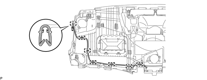
2. REMOVE NO. 1 ANTENNA CORD SUB-ASSEMBLY
(a) Disengage the 7 clamps and remove the No. 1 antenna cord sub-assembly.
3. REMOVE ROOF HEADLINING ASSEMBLY
(See page )
4. REMOVE NO. 2 ANTENNA CORD SUB-ASSEMBLY (w/o Sliding Roof)
(a) Peel up the strips of tape so that the washer hose and No. 2 antenna cord sub-assembly can be removed.
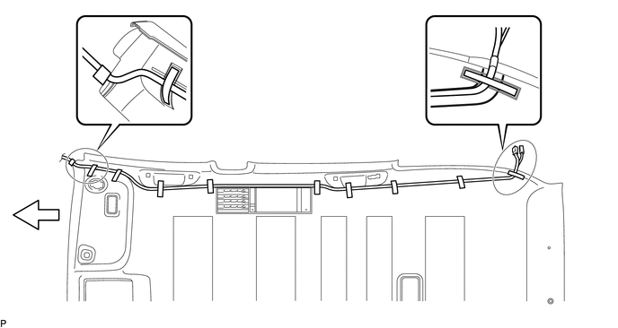 Text in Illustration
 |
Tape |
- |
- |
 |
Front |
- |
- |
HINT:
Tape is not available as a supply part. Try to leave as much tape as possible on the roof headlining so that the tape can be reused.
(b) Remove the washer hose and No. 2 antenna cord sub-assembly from the roof headlining assembly.
5. REMOVE NO. 2 ANTENNA CORD SUB-ASSEMBLY (w/ Sliding Roof)
(a) Peel up the strips of tape so that the washer hose and No. 2 antenna cord sub-assembly can be removed.
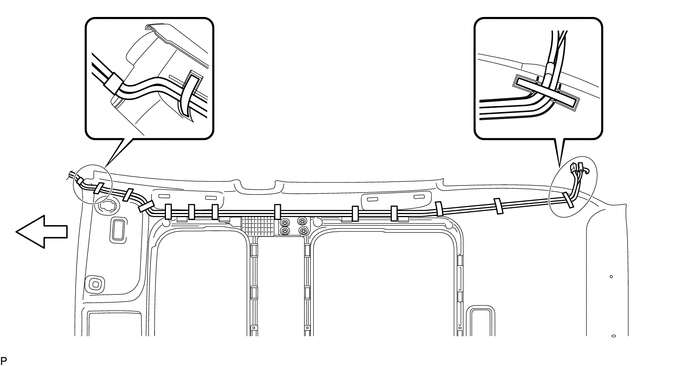 Text in Illustration
|
|
Tape |
- |
- |
|
|
Front |
- |
- |
HINT:
Tape is not available as a supply part. Try to leave as much tape as possible on the roof headlining so that the tape can be reused.
(b) Remove the washer hose and No. 2 antenna cord sub-assembly from the roof headlining assembly.
6. REMOVE UPPER BACK WINDOW PANEL TRIM
7. REMOVE BACK DOOR PANEL TRIM ASSEMBLY
8. REMOVE BACK DOOR TRIM COVER LH (w/o Power Back Door)
9. REMOVE BACK DOOR TRIM COVER LH (w/ Power Back Door)
10. REMOVE BACK DOOR TRIM COVER RH
11. REMOVE NO. 3 ANTENNA CORD SUB-ASSEMBLY
(a) w/o Satellite Radio:
|
(1) Disconnect the 2 connectors. |
|
.png)
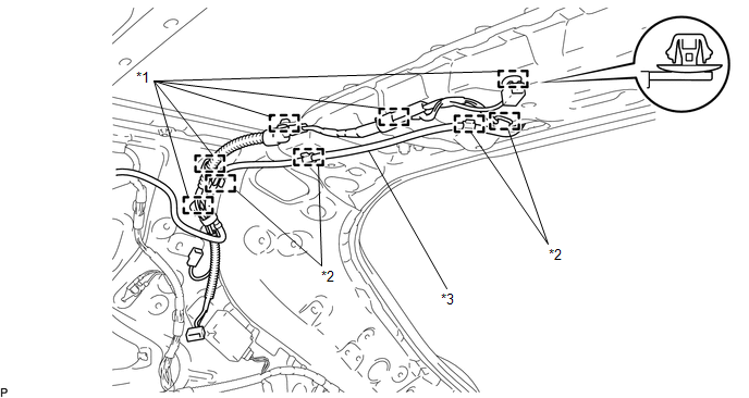
(2) Disengage the 4 hooks and disconnect the washer hose.
(3) Disengage the 7 clamps.
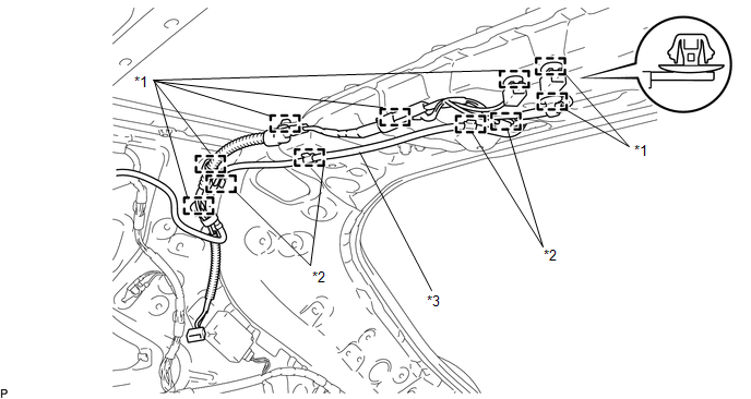 Text in Illustration
|
*1 |
Clamp |
*2 |
Hook |
|
*3 |
Washer Hose |
- |
- |
(b) w/ Satellite Radio:
|
(1) Disconnect the connector. |
|
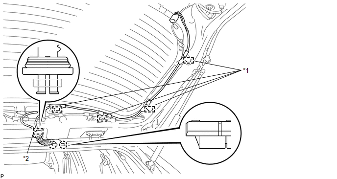
(2) Disengage the 4 hooks and disconnect the washer hose.
(3) Disengage the 5 clamps.
 Text in Illustration
|
*1 |
Clamp |
*2 |
Hook |
|
*3 |
Washer Hose |
- |
- |
|
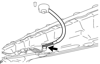
(c) Disconnect the connector and disengage the clamp. |
|
(d) Disengage the 4 clamps.
 Text in Illustration
|
*1 |
Clamp |
*2 |
Grommet |
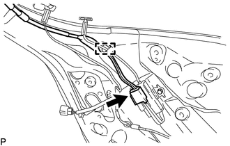
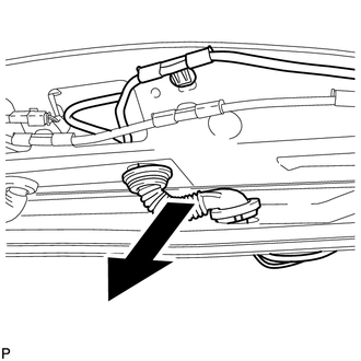
(e) Disconnect the grommet from the back door.
(f) Disengage the 2 claws.
|
(g) Remove the No. 3 antenna cord sub-assembly with the washer hose as shown in the illustration. |
|
 Components
COMPONENTS
ILLUSTRATION
ILLUSTRATION
ILLUSTRATION
ILLUSTRATION
...
 Installation
INSTALLATION
PROCEDURE
1. INSTALL NO. 3 ANTENNA CORD SUB-ASSEMBLY
(a) Pass the washer hose through the No. 3 antenna cord sub-assembly.
(b) Pass the No. 3 antenna cord sub-assembly with ...
Other materials about Toyota Venza:
Windshield Deicer does not Operate
DESCRIPTION
When the rear window defogger switch on the air conditioning control assembly
is pressed, the operation signal is transmitted to the air conditioning amplifier
assembly through the LIN communication line. When the air conditioning amplifier
...
Precaution
PRECAUTION
1. WHEN DISCONNECTING CABLE FROM NEGATIVE BATTERY TERMINAL
NOTICE:
When disconnecting the cable from the negative (-) battery terminal, initialize
the following systems after the cable is reconnected.
System Name
See Proc ...
Portable Player cannot be Registered
CAUTION / NOTICE / HINT
HINT:
Some versions of "Bluetooth" compatible audio players may not function properly,
or the functions may be limited using the radio and display receiver assembly, even
if the portable audio player itself can play file ...

0.1458