Toyota Venza: Tires and wheels
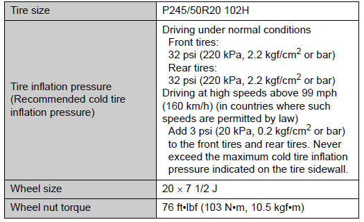
►Type A
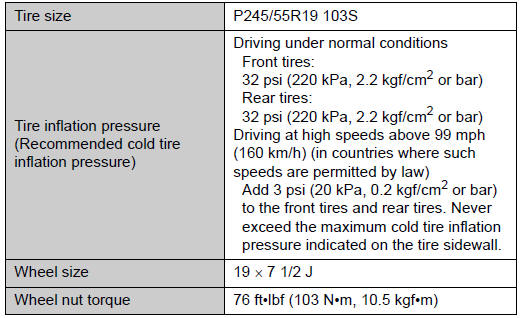
► Type B
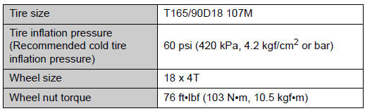
► Spare tire
 Steering
...
 Light bulbs
A: D4S discharge bulbs
B: H11 halogen bulbs
C: HB3 halogen bulbs
D: Wedge base bulbs (amber)
E: Wedge base bulbs (clear)
F: Double end bulbs ...
Other materials about Toyota Venza:
Entire Combination Meter does not Operate
DESCRIPTION
This circuit is the power source circuit for the meter. This circuit provides
two types of power sources; one is a constant power source mainly used as a backup
power source, and the other is an IG power source mainly used for signal transmiss ...
Removal
REMOVAL
PROCEDURE
1. REMOVE REAR WHEELS
2. REMOVE CENTER EXHAUST PIPE ASSEMBLY
(a) Remove the center exhaust pipe assembly.
HINT:
Refer to the instructions for Removal of the exhaust pipe (See page
for 2GR-FE,
for 1AR-FE).
3. REMOVE LOWER NO. 1 EXH ...
Fail-safe Chart
FAIL-SAFE CHART
Engine Coolant Temperature Gauge
Condition
Response
Recovery
Engine coolant temperature data is interrupted for 3 seconds.
The gauge needle indicates below C.
Engine cool ...

0.142