Toyota Venza: Power Window Master Switch
Components
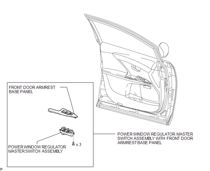
COMPONENTS
ILLUSTRATION
Removal
REMOVAL
PROCEDURE
1. REMOVE POWER WINDOW REGULATOR MASTER SWITCH ASSEMBLY WITH FRONT DOOR ARMREST BASE PANEL
.gif)
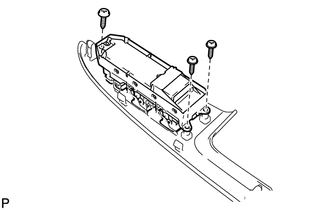
2. REMOVE POWER WINDOW REGULATOR MASTER SWITCH ASSEMBLY
|
(a) Remove the 3 screws and the power window regulator master switch assembly. |
|
Inspection
INSPECTION
PROCEDURE
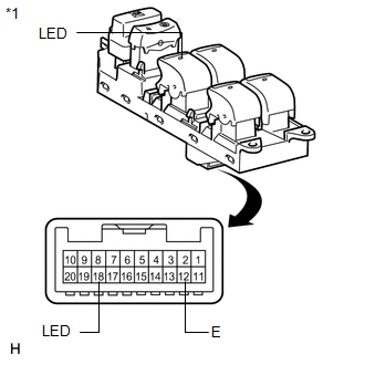
1. INSPECT POWER WINDOW REGULATOR MASTER SWITCH ASSEMBLY
|
(a) Check that the LED illuminates. (1) Apply battery voltage to the power window regulator master switch assembly and check that the LED illuminates. OK:
If the result is not as specified, replace the power window regulator master switch assembly. |
|
Installation
INSTALLATION
PROCEDURE
1. INSTALL POWER WINDOW REGULATOR MASTER SWITCH ASSEMBLY
|
(a) Install the power window regulator master switch assembly with the 3 screws. |
|
.png)
2. INSTALL POWER WINDOW REGULATOR MASTER SWITCH ASSEMBLY WITH FRONT DOOR ARMREST BASE PANEL
.gif)
 Jam Protection Function does not Operate
DESCRIPTION
This symptom may occur for any of the windows.
The jam protection function operates within a specified range during the manual
up or auto up operation.
CAUTION / NOTICE / HINT
NOT ...

Other materials about Toyota Venza:
Precaution
PRECAUTION
1. PRECAUTION FOR DISCONNECTING THE BATTERY CABLE
NOTICE:
When disconnecting the cable from the negative (-) battery terminal, initialize
the following systems after the cable is reconnected:
System
See Procedure
...
Mass or Volume Air Flow Circuit Low Input (P0102,P0103)
DESCRIPTION
The mass air flow meter is a sensor that measures the amount of air flowing through
the throttle valve. The ECM uses this information to determine the fuel injection
time and to provide the appropriate air-fuel ratio.
Inside the mass air flow ...
Maintenance requirements
To ensure safe and economical driving, day-to-day care and regular maintenance
is essential. It is the owner’s responsibility to perform regular checks. Toyota
recommends the following maintenance.
- General maintenance
Should be performed on a d ...

0.1699