Toyota Venza: Terminals Of Ecu
TERMINALS OF ECU
1. CHECK TIRE PRESSURE WARNING ECU
HINT:
Inspect the connectors from the back side while the connectors are connected.

(a) Disconnect the L14 tire pressure warning antenna and receiver connector.
(b) Measure the voltage according to the value(s) in the table below.
|
Terminal No. (Symbol) |
Wiring Color |
Terminal Description |
Condition |
Specified Condition |
|---|---|---|---|---|
|
D31-12 (RDA) - D31-9 (GND) |
Y - W-B |
Tire pressure warning antenna and receiver signal |
Ignition switch ON |
11 to 14 V |
(c) Connect the L14 tire pressure warning antenna and receiver connector.
(d) Measure the voltage and resistance according to the value(s) in the table below. If the result is not as specified, the ECU may have a malfunction.
|
Terminal No. (Symbol) |
Wiring Color |
Terminal Description |
Condition |
Specified Condition |
|---|---|---|---|---|
|
D31-2 (SPD) - D31-9 (GND) |
P - W-B |
Vehicle speed signal |
Vehicle driving |
Pulse generation (see waveform 1) |
|
D31-3 (TC) - D31-9 (GND) |
BR - W-B |
TC terminal |
Terminal TC not connected |
11 to 14 V |
|
D31-4 (TACH) - D31-9 (GND) |
V - W-B |
Engine speed signal |
Engine running |
Pulse generation (see waveform 2) |
|
D31-5 (IND) - D31-9 (GND) |
LG - W-B |
Tire pressure warning light output signal |
|
Below 0.5 V |
|
After ignition switch is turned to ON, tire pressure warning light illuminates for 3 seconds. |
0.9 to 3.2 V |
|||
|
D31-6 (RF5V) - D31-9 (GND) |
R - W-B |
Tire pressure warning antenna and receiver power source |
Ignition switch ON |
11 to 14 V |
|
D31-7 (IG) - D31-9 (GND) |
GR - W-B |
IG power source |
Ignition switch ON |
11 to 14 V |
|
D31-9 (GND) - Body ground |
W-B - Body ground |
Ground |
Always |
Below 1 Ω |
|
D31-10 (SIL) - D31-9 (GND) |
P - W-B |
Diagnostic communication |
Ignition switch ON |
8 to 14 V |
|
D31-11 (GND2) - D31-9 (GND) |
W - W-B |
Tire pressure warning antenna and receiver ground |
Always |
Below 1 Ω |
|
D31-12 (RDA) - D31-9 (GND) |
Y - W-B |
Tire pressure warning antenna and receiver signal |
Ignition switch ON |
11 to 14 V |
(e) Using an oscilloscope, check waveform 1.
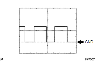 Waveform 1
|
Item |
Content |
|---|---|
|
Terminal |
D31-2 (SPD) - D31-9 (GND) |
|
Tool setting |
5 V/DIV, 20 ms./DIV. |
|
Vehicle condition |
Driving at approximately 20 km/h (12 mph) |
HINT:
The wavelength becomes shorter as the vehicle speed increases.
(f) Using an oscilloscope, check waveform 2.
Waveform 2
|
Item |
Content |
|---|---|
|
Terminal |
D31-4 (TACH) - D31-9 (GND) |
|
Tool setting |
5 V/DIV., 10 ms./DIV. |
|
Vehicle condition |
Idling |
HINT:
The wavelength becomes shorter as the engine speed increases.
 Diagnosis System
DIAGNOSIS SYSTEM
1. CHECK BATTERY VOLTAGE
Standard voltage:
11 to 14 V
If the voltage is below 11 V, recharge the battery before proceeding to the next
step.
2. CHECK DLC3
(a) The ECU uses IS ...
 Dtc Check / Clear
DTC CHECK / CLEAR
1. DTC CHECK (USING SST CHECK WIRE)
(a) Turn the ignition switch off.
(b) Using SST, connect terminals 13 (TC) and 4 (CG) of the DLC3.
SST: 09843-18040
(c) Turn the ignition s ...
Other materials about Toyota Venza:
General Information
GENERAL INFORMATION
A large number of ECU controlled systems are used in this vehicle. In
general, ECU controlled systems are considered to be very intricate, requiring
a high level of technical knowledge to troubleshoot. However, most problem ...
Terminals Of Ecm
TERMINALS OF ECM
HINT:
The standard voltage between each pair of ECM terminals is shown in the table
below. The appropriate conditions for checking each pair of terminals are also indicated.
The result of checks should be compared with the standard vol ...
Front Blower Motor
Components
COMPONENTS
ILLUSTRATION
Installation
INSTALLATION
PROCEDURE
1. INSTALL FRONT BLOWER MOTOR SUB-ASSEMBLY
(a) Install the front blower motor sub-assembly with the 3 screws.
(b) Con ...

0.1435