Toyota Venza: Compressor Lock Sensor Circuit (B1422/22)
SYSTEM DESCRIPTION
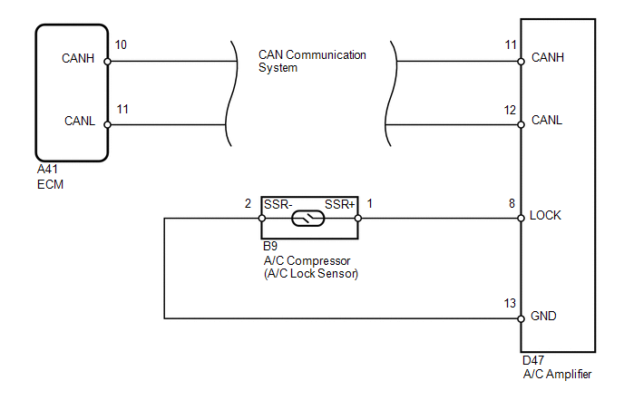
The ECM sends the engine speed signal to the A/C amplifier via CAN communication.
The A/C amplifier reads the difference between compressor speed and engine speed. When the difference becomes too large, the A/C amplifier determines that the compressor is locked, and turns the magnetic clutch off.
|
DTC No. |
DTC Detection Condition |
Trouble Area |
|---|---|---|
|
B1422/22 |
Open or short in compressor lock sensor circuit |
|
WIRING DIAGRAM
PROCEDURE
|
1. |
CHECK CAN COMMUNICATION SYSTEM |
(a) Use the Techstream to check if the CAN communication system is functioning normally.
|
Result |
Proceed to |
|---|---|
|
CAN DTC is not output |
A |
|
CAN DTC is output |
B |
| B | .gif) |
GO TO CAN COMMUNICATION SYSTEM |
|
.gif)
|
2. |
INSPECT A/C COMPRESSOR (A/C LOCK SENSOR) |
|
(a) Disconnect the A/C compressor connector. |
|
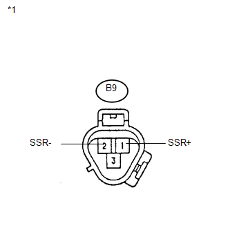
(b) Measure the resistance according to the value(s) in the table below.
Standard Resistance:
|
Tester Connection |
Condition |
Specified Condition |
|---|---|---|
|
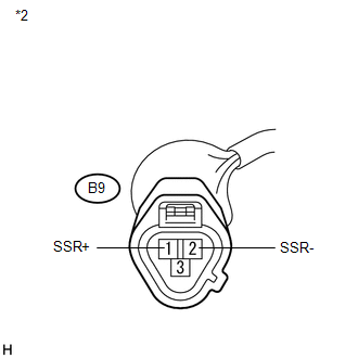
B9-1 (SSR+) - B9-2 (SSR-) |
20°C (68°F) |
160 to 320 Ω |
|
*1 |
Component without harness connected (A/C Compressor) |
| NG | |
REPLACE A/C COMPRESSOR (A/C LOCK SENSOR) |
|
|
3. |
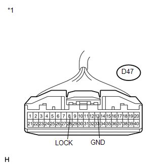
CHECK HARNESS AND CONNECTOR (A/C AMPLIFIER - A/C LOCK SENSOR) |
|
(a) Disconnect the A/C amplifier connector. |
|
|
(b) Measure the resistance according to the value(s) in the table below. Standard Resistance:
Result:
|
|
| A | |
REPAIR OR REPLACE HARNESS OR CONNECTOR |
| B | |
PROCEED TO NEXT SUSPECTED AREA SHOWN IN PROBLEM SYMPTOMS TABLE |
| C | |
REPLACE A/C AMPLIFIER |
 Evaporator Temperature Sensor Circuit (B1413/13)
DESCRIPTION
The evaporator temperature sensor is installed on the evaporator in the air conditioning
unit to detect the cooled air temperature that has passed through the evaporator
and to contro ...
 Room Temperature Sensor Circuit (B1411/11)
DESCRIPTION
The room temperature sensor is installed in the instrument panel. It detects
the cabin temperature to control the air conditioning AUTO mode. The resistance
of the room temperature se ...
Other materials about Toyota Venza:
Problem Symptoms Table
PROBLEM SYMPTOMS TABLE
Use the table below to help determine the cause of problem symptoms. If multiple
suspected areas are listed, the potential causes of the symptoms are listed in order
of probability in the "Suspected Area" column of the tab ...
Door Courtesy Light
Components
COMPONENTS
ILLUSTRATION
Removal
REMOVAL
PROCEDURE
1. REMOVE COURTESY LIGHT ASSEMBLY
(a) Using a screwdriver wrapped with protective tape, disengage the claw.
Text in Illustration
*1
Pro ...
Lost Communication with Front Airbag Sensor RH (B1612/83,B1613/83)
DESCRIPTION
The front airbag sensor RH circuit consists of the center airbag sensor assembly
and front airbag sensor RH.
The front airbag sensor RH detects impacts to the vehicle and sends signals to
the center airbag sensor assembly to determine if the ...

0.1291