Toyota Venza: Diagnosis System
DIAGNOSIS SYSTEM
1. CHECK BATTERY VOLTAGE
Standard voltage:
11 to 14 V
If the voltage is below 11 V, recharge the battery before proceeding to the next step.
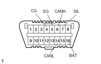
2. CHECK DLC3
(a) The ECU uses ISO 15765-4 for communication. The terminal arrangement of the DLC3 complies with SAE J1962 and matches the ISO 15765-4 format.
|
Symbol (Terminal No.) |
Terminal Description |
Condition |
Specified Condition |
|---|---|---|---|
|
SIL (7) - SG (5) |
Bus "+" line |
During transmission |
Pulse generation |
|
CG (4) - Body ground |
Chassis ground |
Always |
Below 1 Ω |
|
SG (5) - Body ground |
Signal ground |
Always |
Below 1 Ω |
|
BAT (16) - Body ground |
Battery positive |
Always |
11 to 14 V |
|
CANH (6) - CANL (14) |
CAN bus line |
Ignition switch off* |
54 to 69 Ω |
|
CANH (6) - CG (4) |
HIGH-level CAN bus line |
Ignition switch off* |
200 Ω or higher |
|
CANL (14) - CG (4) |
LOW-level CAN bus line |
Ignition switch off* |
200 Ω or higher |
|
CANH (6) - BAT (16) |
HIGH-level CAN bus line |
Ignition switch off* |
6 kΩ or higher |
|
CANL (14) - BAT (16) |
LOW-level CAN bus line |
Ignition switch off* |
6 kΩ or higher |
NOTICE:
*: Before measuring the resistance, leave the vehicle as is for at least 1 minute and do not operate the ignition switch or any other switches or the doors.
(b) If the result is not as specified, the DLC3 may have a malfunction. Repair or replace the harness and connector.
HINT:
Connect the Techstream cable to the DLC3, turn the ignition switch on (IG) and attempt to use the Techstream. If the display indicates that a communication error has occurred, there is a problem either with the vehicle or with the Techstream.
- If communication is normal when the Techstream is connected to another vehicle, inspect the DLC3 of the original vehicle.
- If communication is still not possible when the Techstream is connected to another vehicle, the problem may be in the Techstream itself. Consult the Service Department listed in the Techstream instruction manual.
3. DIAGNOSIS SYSTEM
(a) Warning light
.png)
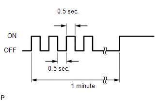
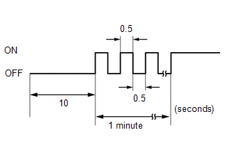
(1) When there is a problem with the tire pressure warning system, the tire pressure warning light blinks at 0.5 second intervals and comes on after 1 minute.
NOTICE:
When the malfunction has been corrected, the tire pressure warning light does not come on.
(b) DTCs (Normal mode)
(1) DTCs are memorized in the tire pressure warning ECU and read by the blinks
of the tire pressure warning light or by using the Techstream (See page
.gif) ).
).
(c) Test mode
(1) By switching from normal mode into test mode (input signal check), you can
inspect the tire pressure warning antenna and receiver, each tire pressure warning
valve and transmitter, engine speed signal and vehicle speed sensor (See page
).
4. CHECK TIRE PRESSURE WARNING LIGHT
(a) Turn the ignition switch to ON.
(b) Check that the tire pressure warning light comes on for 3 seconds.
If the warning check result is not normal, proceed to the troubleshooting for
the tire pressure warning light circuit (See page
).
5. TIRE PRESSURE WARNING LIGHT CHART
HINT:
The table below indicates the tire pressure warning system status according to the tire pressure warning light after the ignition switch is turned to ON.
|
System Status |
Immediately after turning the ignition switch to ON |
Always |
|||||
|---|---|---|---|---|---|---|---|
|
Warning light output pattern |
|||||||
|
Comes on for 3 sec. |
Goes off |
Comes on |
Blinks for 1 minute and then illuminates*1 |
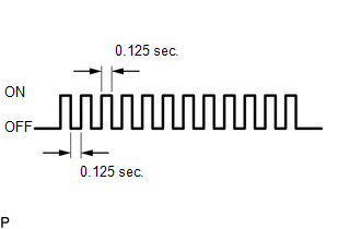
Blinks*2 |
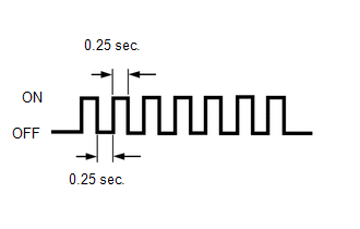
Blinks*3 |
Outputs DTC |
|
|
Normal |
○ |
○ |
- |
- |
- |
- |
- |
|
Low tire pressure |
○ |
- |
○ |
- |
- |
- |
- |
|
System fail |
○ |
- |
- |
○ |
- |
- |
- |
|
Test mode |
○ |
- |
- |
- |
○ |
- |
- |
|
ECU connector poorly connected |
- |
- |
- |
○*4 |
- |
- |
- |
|
TC ground (DTC is output) |
○ |
- |
- |
- |
- |
- |
○ |
|
TC ground (DTC is not output) |
○ |
- |
- |
- |
- |
○ |
- |
- *1: Comes on and goes off repeatedly at 0.5 second intervals, and stays
on after 1 minute.
- *2: Comes on and goes off repeatedly at 0.125 second intervals.
- *3: Comes on and goes off repeatedly at 0.25 second intervals.
- *4: If it is determined that there is a short circuit, the light will
remain off for 10 seconds. It will then blink at 0.5 second intervals and
stay on after 1 minute.
 Test Mode Procedure
TEST MODE PROCEDURE
1. ENTER TEST MODE (SIGNAL CHECK MODE)
(a) Turn the ignition switch off.
(b) Connect the Techstream to the DLC3.
(c) Turn the ignition switch to ON.
(d) Check that the tire pr ...
 Terminals Of Ecu
TERMINALS OF ECU
1. CHECK TIRE PRESSURE WARNING ECU
HINT:
Inspect the connectors from the back side while the connectors are connected.
(a) Disconnect the L14 tire pressure warning antenna and r ...
Other materials about Toyota Venza:
Vehicle load limits
Vehicle load limits include total load capacity, seating capacity, Trailer
Weight Rating (TWR) and cargo capacity.
- Total load capacity (Vehicle capacity weight):
Total load capacity means the combined weight of occupants, cargo and luggage.
&nbs ...
Removal
REMOVAL
PROCEDURE
1. DISCONNECT CABLE FROM NEGATIVE BATTERY TERMINAL
CAUTION:
Wait at least 90 seconds after disconnecting the cable from the negative (-)
battery terminal to disable the SRS system (See page
).
NOTICE:
When disconnecting the cable, s ...
Short in Front Pretensioner Squib RH Circuit (B1900/73-B1903/73)
DESCRIPTION
The front pretensioner squib RH circuit consists of the center airbag sensor
assembly and front seat outer belt assembly RH.
The center airbag sensor assembly uses this circuit to deploy the seat belt pretensioner
when deployment conditions a ...

0.1566