Toyota Venza: Terminals Of Ecu
TERMINALS OF ECU
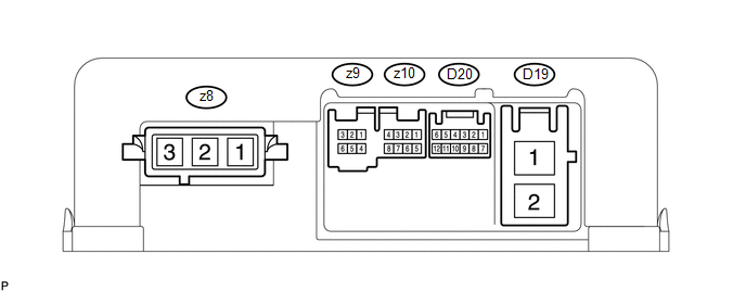
1. CHECK POWER STEERING ECU
HINT:
As connector z8 uses a lock lever, each terminal cannot be checked while the connector is still connected to the power steering ECU.
|
Terminal No. (Symbol) |
Wiring Color |
Terminal Description |
|---|---|---|
|
z8-1 (V) |
W |
V phase motor output |
|
z8-2 (U) |
B |
U phase motor output |
|
z8-3 (W) |
R |
W phase motor output |
(a) Measure the voltage and resistance according to the value(s) in the table below.
NOTICE:
When the P/S warning light is illuminated during a malfunction, the fail-safe function may cause the voltage of the power steering ECU terminals to become 0 V.
|
Terminal No. (Symbol) |
Wiring Color |
Terminal Description |
Condition |
Specified Condition |
|---|---|---|---|---|
|
D19-1 (PIG) - D19-2 (PGND) |
R - B |
Power source |
Always |
11 to 14 V |
|
D19-2 (PGND) - Body ground |
B - Body ground |
Power ground |
Always |
Below 1 Ω |
|
D20-1 (CANH) - D20-7 (CANL) |
BR - W |
CAN communication line |
Ignition switch off |
54 to 69 Ω |
|
D20-6 (IG) - D19-2 (PGND) |
GR - B |
IG power source |
Ignition switch ON |
11 to 14 V |
|
z9-1 (RZV) - D19-2 (PGND) |
R - B |
Rotation angle sensor excitation output signal |
Engine running, steering wheel being turned |
-2.42 to 2.42 V |
|
z9-3 (RZG) - D19-2 (PGND) |
B - B |
Rotation angle sensor excitation circuit GND |
Always |
Below 1 Ω |
|
z9-5 (RZCS) - D19-2 (PGND) |
L - B |
Rotation angle sensor COS aspect output signal |
Engine running, steering wheel being turned |
-0.73 to 0.73 V |
|
z9-6 (RZSN) - D19-2 (PGND) |
Y - B |
Rotation angle sensor SIN aspect output signal |
Engine running, steering wheel being turned |
-0.73 to 0.73 V |
|
z10-5 (TRQ1) - z10-8 (TRQG) |
W - B |
Torque sensor signal |
Engine running, steering wheel not turned (without load) |
2.3 to 2.7 V |
|
Engine running, steering wheel turned to right with vehicle stopped |
2.5 to 3.8 V |
|||
|
Engine running, steering wheel turned to left with vehicle stopped |
1.2 to 2.5 V |
|||
|
z10-6 (TRQV) - z10-8 (TRQG) |
R - B |
Torque sensor voltage source |
Ignition switch ON |
4.5 to 5.5 V |
|
z10-7 (TRQ2) - z10-8 (TRQG) |
Y - B |
Torque sensor signal |
Engine running, steering wheel not turned (without load) |
2.3 to 2.7 V |
|
Engine running, steering wheel turned to right with vehicle stopped |
1.2 to 2.5 V |
|||
|
Engine running, steering wheel turned to left with vehicle stopped |
2.5 to 3.8 V |
|||
|
z10-8 (TRQG) - Body ground |
B - Body ground |
Torque sensor ground |
Always |
Below 1 Ω |
If the result is not as specified, the ECU may have a malfunction.
 Problem Symptoms Table
PROBLEM SYMPTOMS TABLE
HINT:
Use the table below to help determine the cause of problem symptoms.
If multiple suspected areas are listed, the potential causes of the symptoms
are lis ...
 Diagnosis System
DIAGNOSIS SYSTEM
1. CHECK DLC3
(a) Check the DLC3 (See page ).
2. FUNCTION OF P/S WARNING LIGHT
(a) When a malfunction is detected in the power steering system, the P/S warning
light on the acc ...
Other materials about Toyota Venza:
How To Proceed With Troubleshooting
CAUTION / NOTICE / HINT
HINT:
Use the following procedure to troubleshoot the front power seat control
system (w/ Memory).
*: Use the Techstream.
PROCEDURE
1.
VEHICLE BROUGHT TO WORKSHOP
...
Short in GPS Antenna (B15C0,B15C1)
DESCRIPTION
These DTCs are stored when a malfunction occurs in the navigation antenna assembly.
DTC No.
DTC Detection Condition
Trouble Area
B15C0
Navigation antenna malfunction
...
No Signal from Transmitter ID1 (C2121/21-C2124/24,C2181/81-C2184/84)
DESCRIPTION
The tire pressure warning valve and transmitter installed in each tire and wheel
assembly measures the tire pressures. The measured values are transmitted as radio
waves to the tire pressure warning antenna and receiver on the body and then se ...

0.1742