Toyota Venza: Windshield Deicer does not Operate
DESCRIPTION
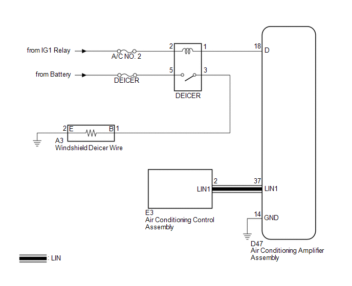
When the rear window defogger switch on the air conditioning control assembly is pressed, the operation signal is transmitted to the air conditioning amplifier assembly through the LIN communication line. When the air conditioning amplifier assembly receives the signal, it turns on the DEICER relay to operate the windshield deicer.
WIRING DIAGRAM
CAUTION / NOTICE / HINT
NOTICE:
Inspect the fuses for circuits related to this system before performing the following inspection procedure.
PROCEDURE
|
1. |
CHECK WINDOW DEFOGGER SYSTEM |
(a) Turn the ignition switch to ON, press the rear window defogger switch, and
check that the window defogger operates (See page
.gif) ).
).
OK:
The window defogger system operates normally.
| NG | .gif) |
GO TO WINDOW DEFOGGER SYSTEM |
|
.gif)
|
2. |
INSPECT DEICER RELAY |
|
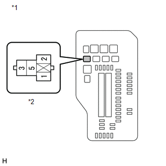
(a) Remove the DEICER relay from the engine room relay block. |
|
.png)
(b) Measure the resistance according to the value(s) in the table below.
Standard Resistance:
|
Tester Connection |
Condition |
Specified Condition |
|---|---|---|
|
3 - 5 |
Battery voltage applied between terminals 1 and 2 |
Below 1 Ω |
|
3 - 5 |
Battery voltage not applied between terminals 1 and 2 |
10 kΩ or higher |
| NG | |
REPLACE DEICER RELAY |
|
|
3. |
CHECK HARNESS AND CONNECTOR (DEICER RELAY POWER SOURCE) |
|
(a) Measure the voltage according to the value(s) in the table below. Standard Voltage:
|
|
| NG | |
REPAIR OR REPLACE HARNESS OR CONNECTOR |
|
|
4. |
CHECK HARNESS AND CONNECTOR (DEICER RELAY - AIR CONDITIONING AMPLIFIER ASSEMBLY) |
|
(a) Disconnect the D47 air conditioning amplifier assembly connector. |
|
(b) Measure the resistance according to the value(s) in the table below.
Standard Resistance:
|
Tester Connection |
Condition |
Specified Condition |
|---|---|---|
|
Engine room relay block DEICER relay terminal 1 - D47-18 (D) |
Always |
Below 1 Ω |
|
D47-14 (GND) - Body ground |
Always |
Below 1 Ω |
|
D47-18 (D) - Body ground |
Always |
10 kΩ or higher |
|
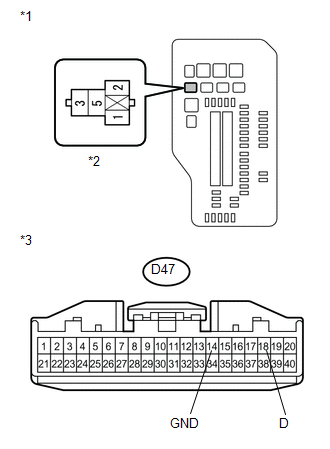
*1 |
Engine Room Relay Block |
|
*2 |
DEICER Relay Terminal |
|
*3 |
Front view of wire harness connector (to Air Conditioning Amplifier Assembly) |
| NG | |
REPAIR OR REPLACE HARNESS OR CONNECTOR |
|
|
5. |
CHECK HARNESS AND CONNECTOR (DEICER RELAY POWER SOURCE) |
|
(a) Measure the voltage according to the value(s) in the table below. Standard Voltage:
|
|
| NG | |
REPAIR OR REPLACE HARNESS OR CONNECTOR |
|
|
6. |
CHECK HARNESS AND CONNECTOR (DEICER RELAY - WINDSHIELD DEICER WIRE) |
|
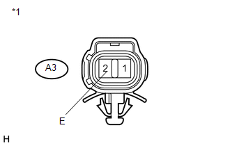
(a) Disconnect the A3 windshield deicer wire connector. |
|
(b) Measure the resistance according to the value(s) in the table below.
Standard Resistance:
|
Tester Connection |
Condition |
Specified Condition |
|---|---|---|
|
A3-1 (B) - engine room relay block DEICER relay terminal 3 |
Always |
Below 1 Ω |
|
A3-1 (B) - Body ground |
Always |
10 kΩ or higher |
|
Engine room relay block DEICER relay terminal 3 - Body ground |
Always |
10 kΩ or higher |
|
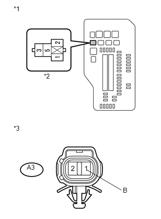
*1 |
Engine Room Relay Block |
|
*2 |
DEICER Relay Terminal |
|
*3 |
Front view of wire harness connector (to Windshield Deicer Wire) |
| NG | |
REPAIR OR REPLACE HARNESS OR CONNECTOR |
|
|
7. |
CHECK HARNESS AND CONNECTOR (WINDSHIELD DEICER WIRE - BODY GROUND) |
|
(a) Measure the resistance according to the value(s) in the table below. Standard Resistance:
|
|
| OK | |
REPLACE WINDSHIELD GLASS (WINDSHIELD DEICER WIRE) |
| NG | |
REPAIR OR REPLACE HARNESS OR CONNECTOR |
 Terminals Of Ecu
TERMINALS OF ECU
1. CHECK AIR CONDITIONING AMPLIFIER ASSEMBLY
(a) Disconnect the D47 air conditioning amplifier assembly connector.
(b) Measure the voltage and resistance according to the value(s ...
 Windshield Glass
...
Other materials about Toyota Venza:
Removal
REMOVAL
CAUTION / NOTICE / HINT
HINT:
Use the same procedure for the RH side and LH side.
The procedure listed below is for the LH side.
PROCEDURE
1. REMOVE REAR WHEEL
2. SEPARATE REAR DISC BRAKE CALIPER ASSEMBLY
3. REMOVE REAR DISC ...
Disposal
DISPOSAL
CAUTION / NOTICE / HINT
CAUTION:
Before performing pre-disposal deployment of any SRS component, review and closely
follow all applicable environmental and hazardous material regulations. Pre-disposal
deployment may be considered hazardous mate ...
Illumination for Panel Switch does not Come on with Tail Switch ON
PROCEDURE
1.
CHECK VEHICLE SIGNAL (OPERATION CHECK)
(a) Enter the "Vehicle Signal Check Mode" screen.
Refer to Check Vehicle Signal in Operation Check (See page
).
...

0.1154