Toyota Venza: Tcm
Components
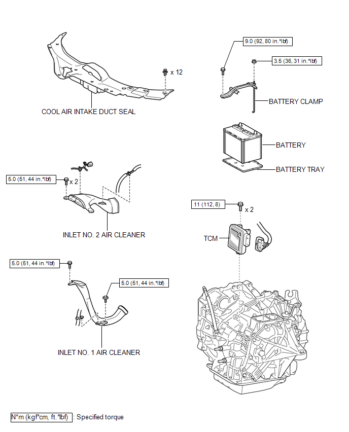
COMPONENTS
ILLUSTRATION
Removal
REMOVAL
CAUTION / NOTICE / HINT
NOTICE:
If automatic transmission parts are replaced, refer to Parts Replacement Compensation
Table to determine if any additional operations are necessary (See page
.gif) ).
).
PROCEDURE
1. DISCONNECT CABLE FROM NEGATIVE BATTERY TERMINAL
NOTICE:
When disconnecting the cable, some systems need to be initialized after the cable
is reconnected (See page ).
2. REMOVE COOL AIR INTAKE DUCT SEAL
3. REMOVE INLET NO. 2 AIR CLEANER
4. REMOVE BATTERY
5. REMOVE INLET NO. 1 AIR CLEANER
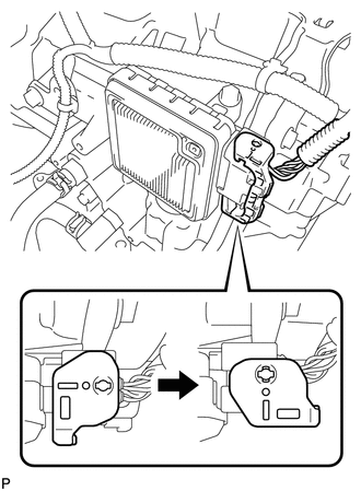
6. REMOVE TCM
|
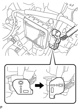
(a) Turn the lock lever and disconnect the connector from the TCM. |
|
|
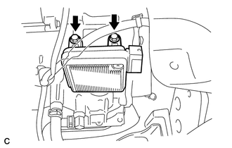
(b) Remove the 2 bolts and TCM from the transaxle. |
|
Installation
INSTALLATION
PROCEDURE
1. INSTALL TCM
(a) Install the TCM to the transaxle.
|
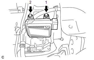
(b) Install and tighten the 2 bolts in the order shown in the illustration. Torque: 11 N·m {112 kgf·cm, 8 ft·lbf} |
|
|
(c) Connect the connector to the TCM. |
|
(d) Turn the lock lever and secure the connector with the lock lever.
2. INSTALL INLET NO. 1 AIR CLEANER
.gif)
3. INSTALL BATTERY
4. INSTALL INLET NO. 2 AIR CLEANER
5. INSTALL COOL AIR INTAKE DUCT SEAL
6. CONNECT CABLE TO NEGATIVE BATTERY TERMINAL
NOTICE:
When disconnecting the cable, some systems need to be initialized after the cable
is reconnected (See page ).
7. CHECK AUTOMATIC TRANSAXLE SYSTEM
NOTICE:
If automatic transmission parts have been replaced, refer to Parts Replacement
Compensation Table to determine if any additional operations are necessary (See
page ).
 Speed Sensor(when Using The Engine Support Bridge)
Components
COMPONENTS
ILLUSTRATION
Removal
REMOVAL
PROCEDURE
1. REMOVE TRANSMISSION VALVE BODY ASSEMBLY
See page
2. REMOVE SPEED SENSOR
(a) Disconnect the speed sensor connector.
...
 Torque Converter And Drive Plate
Inspection
INSPECTION
PROCEDURE
1. INSPECT TORQUE CONVERTER ASSEMBLY
(a) Inspect the one-way clutch.
(1) Press on the serrations of the stator with a finger and rotate it.
Check ...
Other materials about Toyota Venza:
System Description
SYSTEM DESCRIPTION
1. DESCRIPTION OF OCCUPANT CLASSIFICATION SYSTEM
(a) GENERAL DESCRIPTION
(1) In the occupant classification system, the occupant classification ECU calculates
the weight of the occupant based on signals from the occupant classification ...
Satellite Radio Broadcast cannot be Selected or After Selecting Broadcast, Broadcast
cannot be Added into Memory
CAUTION / NOTICE / HINT
NOTICE:
Some satellite radio broadcasts require payment. A contract must be made between
a satellite radio company and the user. If the contract expires, it will not be
possible to listen to the broadcast.
PROCEDURE
1 ...
Installation
INSTALLATION
PROCEDURE
1. INSTALL FUEL PRESSURE REGULATOR ASSEMBLY
(a) Apply a light coat of gasoline to 2 new O-rings, and install them
onto the fuel pressure regulator.
Text in Illustration
*1
New O-r ...

0.128