Toyota Venza: Removal
REMOVAL
CAUTION / NOTICE / HINT
HINT:
- Use the same procedure for the LH side and RH side.
- The following procedure is for the LH side.
PROCEDURE
1. REMOVE ENGINE ASSEMBLY WITH TRANSAXLE (for 2GR-FE)
HINT:
Refer to the procedure up to Remove Engine Assembly with Transaxle (See page
.gif) ).
).
2. REMOVE ENGINE ASSEMBLY WITH TRANSAXLE (for 1AR-FE)
HINT:
Refer to the procedure up to Remove Engine Assembly with Transaxle (See page
).
3. REMOVE FRONT NO. 1 STABILIZER BRACKET LH (for AWD)
4. REMOVE FRONT NO. 1 STABILIZER BRACKET RH (for AWD)
HINT:
Perform the same procedure as for the LH side.
5. REMOVE FRONT STABILIZER BAR WITH FRONT STABILIZER LINK ASSEMBLY (for AWD)
6. REMOVE STEERING LINK ASSEMBLY (for AWD)
7. REMOVE FRONT FRAME ASSEMBLY (for 2GR-FE)
8. SEPARATE REAR ENGINE MOUNTING INSULATOR ASSEMBLY (for 1AR-FE AWD)
9. REMOVE FRONT FRAME ASSEMBLY (for 1AR-FE)
10. REMOVE ENGINE MOUNTING INSULATOR LH (for 2GR-FE)
11. REMOVE ENGINE MOUNTING INSULATOR LH (for 1AR-FE)
12. REMOVE FRONT LOWER SUSPENSION ARM
|
(a) Remove the 3 bolts, nut and front lower suspension arm from the front frame assembly. |
|
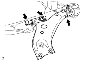
(b) Remove the front lower arm bushing stopper from the front lower suspension arm.
 Components
COMPONENTS
ILLUSTRATION
ILLUSTRATION
ILLUSTRATION
ILLUSTRATION
...
 Installation
INSTALLATION
CAUTION / NOTICE / HINT
HINT:
Use the same procedure for the LH side and RH side.
The following procedure is for the LH side.
PROCEDURE
1. INSTALL FRONT LOWER SUSPE ...
Other materials about Toyota Venza:
Installation
INSTALLATION
PROCEDURE
1. INSTALL FUEL INJECTOR ASSEMBLY
HINT:
Perform "Inspection After Repair" after replacing the fuel injector assembly
(See page ).
(a) Apply a light coat of gasoline or spindle oil to new O-rings, and
then ...
Engine Stall History (P1603,P1605)
DESCRIPTION
P1603
After starting the engine, this DTC is stored when the engine stops without the
ignition switch being operated.
Using the Techstream, the conditions present when the DTC was stored can be confirmed
by referring to the freeze frame data ...
Inspection
INSPECTION
PROCEDURE
1. INSPECT LUMBAR SUPPORT ADJUSTER ASSEMBLY
(a) Check operation of the lumbar support adjuster.
(1) Check if the lumbar support adjuster moves smoothly when the battery is connected
to the lumbar support adjuster motor connector te ...

0.1263