Toyota Venza: Removal
REMOVAL
PROCEDURE
1. REMOVE REAR WHEELS
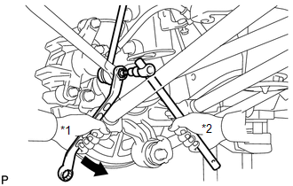
2. REMOVE REAR STABILIZER LINK ASSEMBLY LH
|
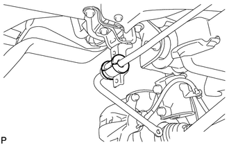
(a) Remove the nut and separate the rear stabilizer link assembly LH from the rear stabilizer bar. Text in Illustration
HINT: If the ball joint turns together with the nut, use a hexagon wrench (5 mm) to hold the stud bolt. |
|
|
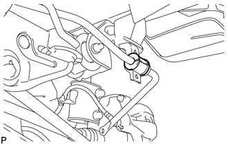
(b) Remove the nut and the rear stabilizer link assembly LH from the rear shock absorber with coil spring LH. Text in Illustration
HINT: If the ball joint turns together with the nut, use a hexagon wrench (5 mm) to hold the stud bolt. |
|
.png)
3. REMOVE REAR STABILIZER LINK ASSEMBLY RH
HINT:
Perform the same procedure as the LH side.
4. REMOVE NO. 1 FLOOR UNDER COVER
.gif)
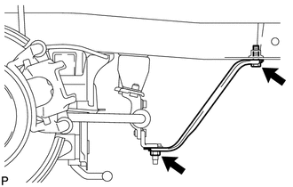
5. REMOVE REAR LOWER SUSPENSION BRACE (for LH Side)
|
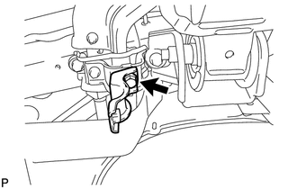
(a) Remove the bolt, the nut and the rear lower suspension brace (LH side). |
|
6. REMOVE REAR LOWER SUSPENSION BRACE (for RH Side)
HINT:
Perform the same procedure as the LH side.
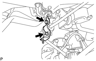
7. REMOVE REAR STABILIZER BAR BRACKET LH (for Rear Side)
|
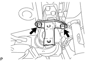
(a) Remove the 2 bolts and the rear stabilizer bar bracket LH (rear side). |
|
8. REMOVE REAR STABILIZER BAR BRACKET RH (for Rear Side)
|
(a) Remove the 2 bolts and the rear stabilizer bar bracket RH (rear side). |
|
9. REMOVE REAR STABILIZER BUSHING (for LH Side)
|
(a) Remove the rear stabilizer bushing (LH side). |
|
10. REMOVE REAR STABILIZER BUSHING (for RH Side)
|
(a) Remove the rear stabilizer bushing (RH side). |
|
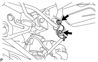
11. REMOVE REAR STABILIZER BAR BRACKET LH (for Front Side)
|
(a) Remove the bolt and the rear stabilizer bar bracket LH (front side). |
|
12. REMOVE REAR STABILIZER BAR BRACKET RH (for Front Side)
|
(a) Remove the 2 bolts and the rear stabilizer bar bracket RH (front side). |
|
 Inspection
INSPECTION
PROCEDURE
1. INSPECT REAR STABILIZER LINK ASSEMBLY
(a) Move the ball joint stud back and forth 5 times before installing
the nut as shown in the illustration.
...
 Installation
INSTALLATION
PROCEDURE
1. TEMPORARILY INSTALL REAR STABILIZER BAR BRACKET LH (for Front Side)
(a) Temporarily install the rear stabilizer bar bracket LH (front side)
with the bolt.
...
Other materials about Toyota Venza:
Seat belts
Make sure that all occupants are wearing their seat belts before driving the
vehicle.
- Correct use of the seat belts
1. Extend the shoulder belt so that it comes fully over the shoulder, but does
not come into contact with the neck or slide off ...
Malfunction in Deceleration Sensor (C1245/93)
DESCRIPTION
If a malfunction in the deceleration sensor circuit occurs, the AWD control ECU
will output this DTC.
DTC No.
DTC Detecting Condition
Trouble Area
C1296/96
When the following conditio ...
BUS IC Communication Malfunction (B1497/97)
DESCRIPTION
The air conditioning harness connects the A/C amplifier and each servo. The A/C
amplifier supplies power and sends operation instructions to each servo through
the air conditioning harness. Each servo sends the damper position information to
...

0.1747