Toyota Venza: Speed Sensor(when Using The Engine Support Bridge)
Components
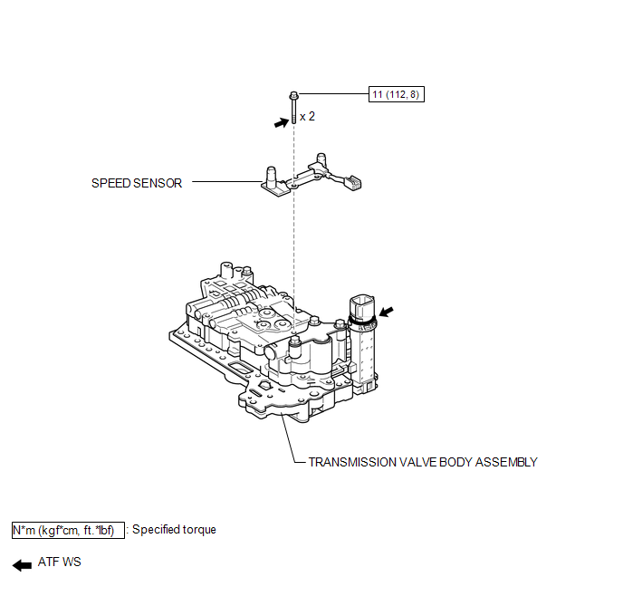
COMPONENTS
ILLUSTRATION
Removal
REMOVAL
PROCEDURE
1. REMOVE TRANSMISSION VALVE BODY ASSEMBLY
See page .gif)
2. REMOVE SPEED SENSOR
(a) Disconnect the speed sensor connector.
|
(b) Remove the 2 bolts and speed sensor from the transmission valve body assembly. |
|
.png)
Installation
INSTALLATION
PROCEDURE
1. INSTALL SPEED SENSOR
|
(a) Coat the 2 bolts with ATF. |
|
.png)
(b) Install the speed sensor to the transmission valve body assembly with the 2 bolts.
Torque:
11 N·m {112 kgf·cm, 8 ft·lbf}
(c) Connect the speed sensor connector.
2. INSTALL TRANSMISSION VALVE BODY ASSEMBLY
See page .gif)
 Speed Sensor(when Not Using The Engine Support Bridge)
Components
COMPONENTS
ILLUSTRATION
Removal
REMOVAL
PROCEDURE
1. REMOVE AUTOMATIC TRANSAXLE ASSEMBLY
HINT:
See the steps from "Remove Engine Assembly with transaxle" through &qu ...
 Tcm
Tcm
Components
COMPONENTS
ILLUSTRATION
Removal
REMOVAL
CAUTION / NOTICE / HINT
NOTICE:
If automatic transmission parts are replaced, refer to Parts Replacement Compensation
Table to determi ...
Other materials about Toyota Venza:
ECU Power Source Circuit
DESCRIPTION
This is the power source for the tire pressure warning ECU.
WIRING DIAGRAM
CAUTION / NOTICE / HINT
NOTICE:
When replacing the tire pressure warning ECU, read the transmitter IDs
stored in the old ECU using the Techstream and writ ...
Inspection
INSPECTION
PROCEDURE
1. INSPECT FRONT SHOCK ABSORBER ASSEMBLY
(a) Compress and extend the shock absorber rod 4 or more times.
Standard:
There is no abnormal resistance or sound and operation resistance is
normal.
HINT:
If there i ...
Starter Signal Circuit
DESCRIPTION
1. w/o Smart Key System
While the engine is being cranked, current flows from terminal ST1 of the ignition
switch assembly to the park/neutral position switch assembly and also flows to terminal
STA of the ECM (STA Signal).
2. w/ Smart Key S ...

0.1658