Toyota Venza: Tachometer Malfunction
DESCRIPTION
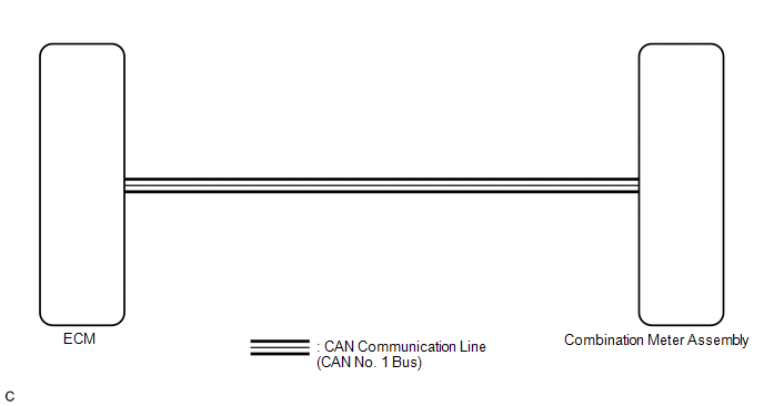
In this circuit, the meter CPU receives engine speed signals from the ECM using the CAN communication system (CAN No. 1 Bus). The meter CPU displays the engine speed calculated based on the data received from the ECM.
WIRING DIAGRAM
PROCEDURE
|
1. |
CHECK CAN COMMUNICATION SYSTEM |
(a) Check if a CAN communication DTC is output (See page
.gif) ).
).
|
Result |
Proceed to |
|---|---|
|
CAN communication DTC is not output. |
A |
|
CAN communication DTC is output. |
B |
| B | .gif) |
GO TO CAN COMMUNICATION SYSTEM |
|
.gif)
|
2. |
PERFORM ACTIVE TEST USING TECHSTREAM (TACHO METER OPERATION) |
(a) Connect the Techstream to the DLC3.
(b) Turn the ignition switch to ON.
(c) Turn the Techstream on.
(d) Enter the following menus: Body Electrical / Combination Meter / Active Test.
(e) Check the operation by referring to the table below.
Combination Meter|
Tester Display |
Test Part |
Control Range |
Diagnostic Note |
|---|---|---|---|
|
Tacho Meter Operation |
Tachometer |
0, 1000, 2000, 3000, 4000, 5000, 6000, 7000 (rpm) |
Confirm that the vehicle is stopped with the engine idling |
OK:
Tachometer indication is normal.
| NG | |
REPLACE COMBINATION METER ASSEMBLY |
|
|
3. |
READ VALUE USING TECHSTREAM (ENGINE RPM) |
(a) Connect the Techstream to the DLC3.
(b) Turn the ignition switch to ON.
(c) Turn the Techstream on.
(d) Enter the following menus: Body Electrical / Combination Meter / Data List.
(e) Check the values by referring to the table below.
Combination Meter|
Tester Display |
Measurement Item/Range |
Normal Condition |
Diagnostic Note |
|---|---|---|---|
|
Engine Rpm |
Engine speed/Min.: 0 rpm, Max.: 12750 rpm |
650 to 750 rpm (When idling) |
If data received from the ECM exceeds the range that can be displayed on the meter, the meter continues to display the maximum value of the range. |
OK:
Engine speed displayed on the Techstream is almost the same as the tachometer indication.
| NG | |
REPLACE COMBINATION METER ASSEMBLY |
|
|
4. |
READ VALUE USING TECHSTREAM (ENGINE SPEED) |
(a) Connect the Techstream to the DLC3.
(b) Turn the ignition switch to ON.
(c) Turn the Techstream on.
(d) Enter the following menus: Powertrain / Engine and ECT / Data List.
(e) Check the values by referring to the table below.
Engine and ECT|
Tester Display |
Measurement Item/Range |
Normal Condition |
Diagnostic Note |
|---|---|---|---|
|
Engine Speed |
Engine speed/Min.: 0 rpm, Max.: 16383.75 rpm |
650 to 750 rpm (When idling) |
- |
OK:
Engine speed displayed on the Techstream is almost the same as the Techstream indication (Body Electrical / Combination Meter / Data List).
|
Result |
Proceed to |
|---|---|
|
OK |
A |
|
NG (for 2GR-FE) |
B |
|
NG (for 1AR-FE) |
C |
| B | |
GO TO SFI SYSTEM (for 2GR-FE) |
| C | |
GO TO SFI SYSTEM (for 1AR-FE) |
|
|
5. |
REPLACE ECM |
(a) Replace the ECM with a new or a known good one (See page
for 2GR-FE,
for 1AR-FE).
OK:
The operation of the tachometer returns to normal.
| OK | |
END |
| NG | |
REPLACE COMBINATION METER ASSEMBLY |
 Speedometer Malfunction
DESCRIPTION
The meter CPU receives vehicle speed signals from the skid control ECU via the
CAN communication system (CAN No. 1 Bus). The speed sensor detects the wheel speed
and sends the appropr ...
 Engine Coolant Temperature Receiver Gauge Malfunction
DESCRIPTION
In this circuit, the meter CPU receives engine coolant temperature signals from
the ECM using the CAN communication system (CAN No. 1 Bus). The meter CPU displays
engine coolant tempe ...
Other materials about Toyota Venza:
Winter driving tips
Carry out the necessary preparations and inspections before driving the vehicle
in winter. Always drive the vehicle in a manner appropriate to the prevailing weather
conditions.
- Pre-winter preparations
• Use fluids that are appropriate to the p ...
System Description
SYSTEM DESCRIPTION
1. ILLUMINATED ENTRY SYSTEM
(a) The illuminated entry system has the following control functions:
Control
Outline
Lights that Operate
Actuation Area-linked*2
When a registered k ...
Throttle Actuator Control Motor Current Range / Performance (P2118)
DESCRIPTION
The electronic throttle control system has a dedicated power supply circuit.
The voltage (+BM) is monitored and when it is low (below 4 V), the ECM determines
that there is a malfunction in the electronic throttle control system and cuts off
...

0.1741