Toyota Venza: Air Conditioning Compressor Magnetic Clutch Circuit
DESCRIPTION
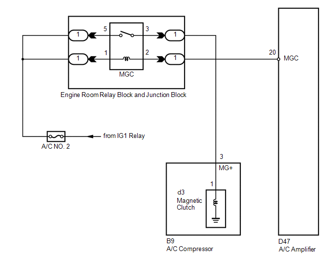
When the A/C amplifier is turned on, a magnetic clutch ON signal is sent from the MGC terminal of the A/C amplifier. Then, the MGC relay turns on to operate the magnetic clutch.
WIRING DIAGRAM
CAUTION / NOTICE / HINT
NOTICE:
Inspect the fuses for circuits related to this system before performing the following inspection procedure.
PROCEDURE
|
1. |
CHECK CAN COMMUNICATION SYSTEM |
(a) Use the Techstream to check if the CAN communication system is functioning normally.
|
Result |
Proceed to |
|---|---|
|
CAN DTC is not output |
A |
|
CAN DTC is output |
B |
| B | .gif) |
GO TO CAN COMMUNICATION SYSTEM |
|
.gif)
|
2. |
INSPECT RELAY (MGC) |
|
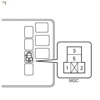
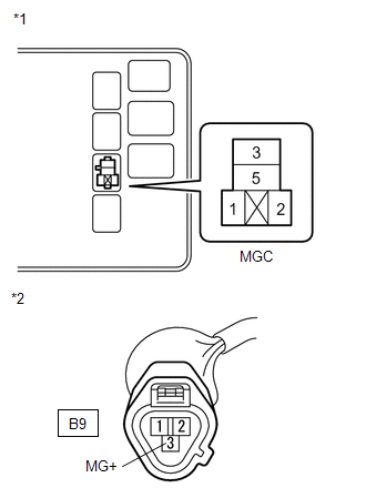
(a) Remove the MGC relay from the engine room relay block and junction block. |
|
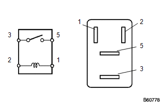
(b) Measure the resistance according to the value(s) in the table below.
Standard Resistance:
|
Tester Connection |
Specified Condition |
|---|---|
|
3 - 5 |
10 kΩ or higher |
|
3 - 5 |
Below 1 Ω (when battery voltage is applied to terminals 1 and 2) |
| NG | |
REPLACE RELAY (MGC) |
|
|
3. |
CHECK HARNESS AND CONNECTOR (ENGINE ROOM RELAY BLOCK AND JUNCTION BLOCK - BATTERY) |
|
(a) Remove the MGC relay from the engine room relay block and junction block. |
|
(b) Measure the voltage according to the value(s) in the table below.
Standard Voltage:
|
Tester Connection |
Condition |
Specified Condition |
|---|---|---|
|
Relay block MGC relay terminal 1 - Body ground |
Ignition switch ON |
11 to 14 V |
|
*1 |
Component without relay installed (Engine Room Relay Block and Junction Block) |
| NG | |
REPAIR OR REPLACE HARNESS OR CONNECTOR |
|
|
4. |
CHECK HARNESS AND CONNECTOR (A/C AMPLIFIER - BATTERY) |
|
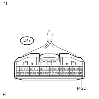
(a) Disconnect the A/C amplifier connector. |
|
(b) Measure the voltage according to the value(s) in the table below.
Standard Voltage:
|
Tester Connection |
Condition |
Specified Condition |
|---|---|---|
|
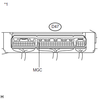
D47-20 (MGC) - Body ground |
Ignition switch off |
Below 1 V |
|
D47-20 (MGC) - Body ground |
Ignition switch ON |
11 to 14 V |
|
*1 |
Front view of wire harness connector (to A/C Amplifier) |
| NG | |
REPAIR OR REPLACE HARNESS OR CONNECTOR |
|
|
5. |
INSPECT A/C AMPLIFIER |
|
(a) Reconnect the A/C amplifier connector. |
|
(b) Measure the voltage according to the value(s) in the table below.
Standard Voltage:
|
Tester Connection |
Condition |
Specified Condition |
|---|---|---|
|
D47-20 (MGC) - Body ground |
Ignition switch ON A/C switch: off |
11 to 14 V |
|
D47-20 (MGC) - Body ground |
Ignition switch ON A/C switch: on |
Below 1 V |
|
*1 |
Component with harness connected (A/C Amplifier) |
| NG | |
REPLACE A/C AMPLIFIER |
|
|
6. |
INSPECT A/C COMPRESSOR |
|
(a) Disconnect the A/C compressor connector. |
|
|
(b) Disconnect the magnetic clutch connector. |
|
(c) Measure the resistance according to the value(s) in the table below.
Standard Resistance:
|
Tester Connection |
Condition |
Specified Condition |
|---|---|---|
|
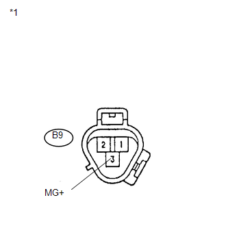
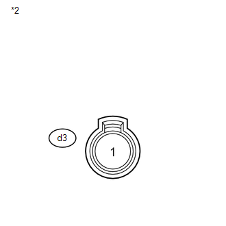
B9-3 (MG+) - d3-1 |
Always |
Below 1 Ω |
|
B9-3 (MG+) - Body ground |
Always |
10 kΩ or higher |
|
*1 |
Component without harness connected (A/C Compressor) |
|
*2 |
Component without harness connected (Magnetic Clutch) |
| NG | |
REPLACE A/C COMPRESSOR |
|
|
7. |
INSPECT MAGNETIC CLUTCH |
|
(a) Measure the resistance according to the value(s) in the table below. Standard Resistance:
|
|
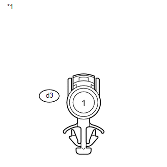
(b) When connector terminal d3-1 is connected to a positive (+) battery terminal, check that the following occurs: 1) the magnetic clutch operating sound can be heard, and 2) the magnetic clutch hub and rotor lock.
Text in Illustration|
*1 |
Component without harness connected (Magnetic Clutch) |
| NG | |
REPLACE MAGNETIC CLUTCH |
|
|
8. |
CHECK HARNESS AND CONNECTOR (ENGINE ROOM RELAY BLOCK AND JUNCTION BLOCK - BATTERY) |
|
(a) Remove the MGC relay from the engine room relay block and junction block. |
|
(b) Measure the voltage according to the value(s) in the table below.
Standard Voltage:
|
Tester Connection |
Condition |
Specified Condition |
|---|---|---|
|
Relay block MGC relay terminal 5 - Body ground |
Ignition switch ON |
11 to 14 V |
|
*1 |
Component without relay installed (Engine Room Relay Block and Junction Block) |
| NG | |
REPAIR OR REPLACE HARNESS OR CONNECTOR |
|
|
9. |
CHECK HARNESS AND CONNECTOR (ENGINE ROOM RELAY BLOCK AND JUNCTION BLOCK - A/C COMPRESSOR) |
|
(a) Measure the resistance according to the value(s) in the table below. Standard Resistance:
Result:
|
|
| A | |
REPAIR OR REPLACE HARNESS OR CONNECTOR |
| B | |
PROCEED TO NEXT SUSPECTED AREA SHOWN IN PROBLEM SYMPTOMS TABLE |
| C | |
REPLACE A/C AMPLIFIER |
 Air Conditioning Control Panel Circuit
DESCRIPTION
This circuit consists of the air conditioning control assembly and the A/C amplifier.
When the air conditioning control assembly is operated, signals are transmitted
to the A/C amplif ...
 Blower Motor Circuit
DESCRIPTION
The blower motor is operated by signals from the A/C amplifier. Blower motor
speed signals are transmitted in accordance with changes in the duty ratio.
WIRING DIAGRAM
CAUTION / NOT ...
Other materials about Toyota Venza:
System Diagram
SYSTEM DIAGRAM
Communication Table
Transmitting ECU
(Transmitter)
Receiving ECU
(Receiver)
Signal
Communication Method
Combination meter
Power management control ECU
...
Disassembly
DISASSEMBLY
PROCEDURE
1. REMOVE TAIL AND STOP LIGHT BULB
(a) Turn the tail and stop light bulb and the rear combination light
socket and wire in the direction indicated by the arrow shown in the illustration,
and remove them as a unit.
...
Data List / Active Test
DATA LIST / ACTIVE TEST
1. DATA LIST
HINT:
Using the Techstream to read the Data List allows the values or states of switches,
sensors, actuator and other items to be read without removing any parts. This non-intrusive
inspection can be very useful beca ...

0.131