Toyota Venza: Speedometer Malfunction
DESCRIPTION
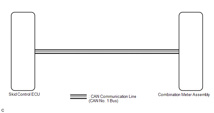
The meter CPU receives vehicle speed signals from the skid control ECU via the CAN communication system (CAN No. 1 Bus). The speed sensor detects the wheel speed and sends the appropriate signals to the skid control ECU. The skid control ECU supplies power to the vehicle speed sensor. The skid control ECU detects vehicle speed signals based on the pulses of the voltage.
HINT:
- Factors that affect the indicated vehicle speed include tire size, tire
inflation, and tire wear. The speed indicated on the speedometer has an
allowable margin of error. This can be tested using a speedometer tester
(calibrated chassis dynamometer). For details about testing and the margin
of error, see the reference chart (See page
.gif) ).
). - If the vehicle speed sensor circuit has a malfunction, the skid control
ECU outputs the DTCs. Refer to troubleshoot Brake Control System (See page
).
WIRING DIAGRAM
CAUTION / NOTICE / HINT
NOTICE:
If the vehicle speed is outside the allowable range when tested, perform the
following procedure (See page ).
HINT:
Before starting the following inspection, check tire size and tire air pressure.
PROCEDURE
|
1. |
CHECK CAN COMMUNICATION SYSTEM |
(a) Check if a CAN communication DTC is output (See page
).
|
Result |
Proceed to |
|---|---|
|
CAN communication DTC is not output. |
A |
|
CAN communication DTC is output. |
B |
| B | .gif) |
GO TO CAN COMMUNICATION SYSTEM |
|
.gif)
|
2. |
PERFORM ACTIVE TEST USING TECHSTREAM (SPEED METER OPERATION) |
(a) Connect the Techstream to the DLC3.
(b) Turn the ignition switch to ON.
(c) Turn the Techstream on.
(d) Enter the following menus: Body Electrical / Combination Meter / Active Test.
(e) Check the operation by referring to the table below.
Combination Meter|
Tester Display |
Test Part |
Control Range |
Diagnostic Note |
|---|---|---|---|
|
Speed Meter Operation |
Speedometer |
0, 40, 80, 120, 160, 200, 240 km/h |
Confirm that the vehicle is stopped with the engine idling |
|
Acceptable range (km/h): [Control range → Speedometer display]
|
OK:
Speedometer indication is normal.
| NG | |
REPLACE COMBINATION METER ASSEMBLY |
|
|
3. |
READ VALUE USING TECHSTREAM (VEHICLE SPEED METER) |
(a) Connect the Techstream to the DLC3.
(b) Turn the ignition switch to ON.
(c) Turn the Techstream on.
(d) Enter the following menus: Body Electrical / Combination Meter / Data List.
(e) Check the values by referring to the table below.
Combination Meter|
Tester Display |
Measurement Item/Range |
Normal Condition |
Diagnostic Note |
|---|---|---|---|
|
Vehicle Speed Meter |
Vehicle speed/Min.: 0 km/h (0 mph), Max.: 255 km/h (158 mph) |
Almost the same as actual vehicle speed (Speedometer tester) |
- |
OK:
Vehicle speed displayed on the Techstream is almost the same as the actual vehicle speed measured using a speedometer tester (calibrated chassis dynamometer).
| OK | |
REPLACE COMBINATION METER ASSEMBLY |
|
|
4. |
READ VALUE USING TECHSTREAM (FR/FL/RR/RL WHEEL SPEED) |
(a) Connect the Techstream to the DLC3.
(b) Turn the ignition switch to ON.
(c) Turn the Techstream on.
(d) Enter the following menus: Chassis / ABS/VSC/TRAC / Data List.
(e) Check the values by referring to the table below.
ABS/VSC/TRAC|
Tester Display |
Measurement Item/Range |
Normal Condition |
Diagnostic Note |
|---|---|---|---|
|
FR Wheel Speed |
Vehicle speed/Min.: 0 mph (0 km/h), Max.: 202 mph (326 km/h) |
Almost the same as actual vehicle speed (Speedometer tester) |
- |
|
FL Wheel Speed |
Vehicle speed/Min.: 0 mph (0 km/h), Max.: 202 mph (326 km/h) |
Almost the same as actual vehicle speed (Speedometer tester) |
- |
|
RR Wheel Speed |
Vehicle speed/Min.: 0 mph (0 km/h), Max.: 202 mph (326 km/h) |
Almost the same as actual vehicle speed (Speedometer tester) |
- |
|
RL Wheel Speed |
Vehicle speed/Min.: 0 mph (0 km/h), Max.: 202 mph (326 km/h) |
Almost the same as actual vehicle speed (Speedometer tester) |
- |
OK:
Vehicle speed displayed on the Techstream is almost the same as the actual vehicle speed measured using a speedometer tester (calibrated chassis dynamometer).
| NG | |
GO TO BRAKE CONTROL SYSTEM |
|
|
5. |
REPLACE SKID CONTROL ECU |
(a) Replace the skid control ECU with a new or a known good one (See page
).
OK:
The operation of the speedometer returns to normal.
| OK | |
END |
| NG | |
REPLACE COMBINATION METER ASSEMBLY |
 Entire Combination Meter does not Operate
DESCRIPTION
This circuit is the power source circuit for the meter. This circuit provides
two types of power sources; one is a constant power source mainly used as a backup
power source, and the ...
 Tachometer Malfunction
DESCRIPTION
In this circuit, the meter CPU receives engine speed signals from the ECM using
the CAN communication system (CAN No. 1 Bus). The meter CPU displays the engine
speed calculated based ...
Other materials about Toyota Venza:
Removal
REMOVAL
PROCEDURE
1. REMOVE AIR CONDITIONING UNIT ASSEMBLY
(See page )
2. REMOVE NO. 1 FINISH PANEL MOUNTING BRACKET
3. REMOVE NO. 2 FINISH PANEL MOUNTING BRACKET
4. REMOVE NO. 3 AIR DUCT SUB-ASSEMBLY
5. REMOVE NO. 2 AIR DUCT SUB-ASSEMBLY
...
Inspection
INSPECTION
PROCEDURE
1. INSPECT FRONT LOWER BALL JOINT
(a) Inspect the turning torque of the ball joint.
(1) Secure the front lower ball joint in a vise using aluminum plates.
(2) Install the nut to the front lower ball joint stud.
(3) U ...
Installation
INSTALLATION
PROCEDURE
1. INSTALL ENGINE SWITCH
(a) Attach the 2 claws to install the engine switch.
2. INSTALL LOWER INSTRUMENT PANEL FINISH PANEL ASSEMBLY
(a) Connect the connector.
...

0.1405