Toyota Venza: Adjustment
ADJUSTMENT
CAUTION / NOTICE / HINT
.png)
CAUTION:
Before adjusting the door positions of vehicles equipped with side and curtain shield airbags, be sure to disconnect the battery. After adjustment, check that the SRS warning light is operating normally and there are no SRS DTCs output.
HINT:
- Use the same procedure for the RH side and LH side.
- The procedure listed below is for the LH side.
- Centering bolts are used to mount the door hinge to the vehicle body and door. The door cannot be adjusted with the centering bolts installed. Substitute the centering bolts with standard bolts when making adjustments.
- Specified torque for standard bolts is shown in the standard bolt chart
(See page
.gif) ).
).
PROCEDURE
1. INSPECT REAR DOOR
(a) Check that the clearance measurements of areas *1 through *19 are within each standard range.
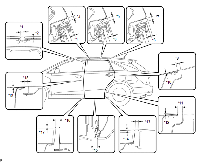 Standard Clearance
|
Area |
Measurement |
Area |
Measurement |
|---|---|---|---|
|
*1 |
2.5 to 6.5 mm (0.0984 to 0.256 in.) |
*11 |
3.0 to 6.0 mm (0.118 to 0.236 in.) |
|
*2 |
-2.0 to 2.0 mm (-0.0787 to 0.0787 in.) |
*12 |
-1.5 to 1.5 mm (-0.0591 to 0.0591 in.) |
|
*3 |
3.5 to 6.5 mm (0.138 to 0.256 in.) |
*13 |
3.2 to 7.2 mm (0.126 to 0.283 in.) |
|
*4 |
0.5 to 3.5 mm (0.0197 to 0.138 in.) |
*14 |
-2.0 to 2.0 mm (-0.0787 to 0.0787 in.) |
|
*5 |
3.5 to 6.5 mm (0.138 to 0.256 in.) |
*15 |
9.3 to 13.3 mm (0.366 to 0.524 in.) |
|
*6 |
0.4 to 3.4 mm (0.0156 to 0.134 in.) |
*16 |
3.2 to 7.2 mm (0.126 to 0.283 in.) |
|
*7 |
3.5 to 6.5 mm (0.138 to 0.256 in.) |
*17 |
-2.0 to 2.0 mm (-0.0787 to 0.0787 in.) |
|
*8 |
1.4 to 4.4 mm (0.0551 to 0.173 in.) |
*18 |
3.0 to 6.0 mm (0.118 to 0.236 in.) |
|
*9 |
3.0 to 6.0 mm (0.118 to 0.236 in.) |
*19 |
-1.5 to 1.5 mm (-0.0591 to 0.0591 in.) |
|
*10 |
-1.5 to 1.5 mm (-0.0591 to 0.0591 in.) |
- |
- |
2. DISCONNECT CABLE FROM NEGATIVE BATTERY TERMINAL
CAUTION:
Wait at least 90 seconds after disconnecting the cable from the negative (-)
battery terminal to disable the SRS system (See page
).
NOTICE:
When disconnecting the cable, some systems need to be initialized after the cable
is reconnected (See page ).
3. ADJUST REAR DOOR
|
(a) Using SST, loosen the hinge bolts on the vehicle body and adjust the door position. SST: 09812-00010 |
|
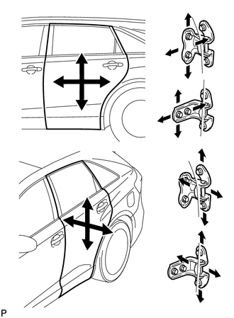
(b) Tighten the hinge bolts on the vehicle body after the adjustment.
Torque:
26 N·m {265 kgf·cm, 19 ft·lbf}
(c) Loosen the hinge bolts on the door and adjust the door position.
(d) Tighten the hinge bolts on the door after the adjustment.
Torque:
26 N·m {265 kgf·cm, 19 ft·lbf}
|
(e) Using a T40 "TORX" socket wrench, slightly loosen the striker mounting screws. |
|
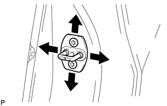
(f) Using a brass bar and a hammer, hit the striker to adjust its position.
(g) Using a T40 "TORX" socket wrench, tighten the striker mounting screws after the adjustment.
Torque:
23 N·m {235 kgf·cm, 17 ft·lbf}
4. CONNECT CABLE TO NEGATIVE BATTERY TERMINAL
NOTICE:
When disconnecting the cable, some systems need to be initialized after the cable
is reconnected (See page ).
5. INSPECT SRS WARNING LIGHT
(See page )
 Disassembly
DISASSEMBLY
PROCEDURE
1. DISCONNECT CABLE FROM NEGATIVE BATTERY TERMINAL
NOTICE:
When disconnecting the cable, some systems need to be initialized after the cable
is reconnected (See page ).
2 ...
 Reassembly
REASSEMBLY
PROCEDURE
1. REPAIR INSTRUCTION
2. INSTALL REAR DOOR OUTSIDE MOULDING
3. INSTALL REAR DOOR LOWER OUTSIDE STRIPE
4. INSTALL NO. 2 BLACK OUT TAPE
5. INSTALL REAR DOOR OUTSID ...
Other materials about Toyota Venza:
Installation
INSTALLATION
PROCEDURE
1. INSTALL STEREO COMPONENT TUNER ASSEMBLY
2. INSTALL NAVIGATION WIRE
(a) Connect the 3 connectors to install the navigation wire.
3. INSTALL STEREO COMPONENT TUNER ASSEMBLY WITH WIRE
(a) Install the stereo component tuner assembly ...
Tire information
Typical tire symbols
►Standard tire
►Compact spare tire
1. Tire size
2. DOT and Tire Identification Number (TIN)
3. Location of treadwear indicators
4. Tire ply composition and materials Plies are layers of rubber-coated parallel
cords ...
System Description
SYSTEM DESCRIPTION
1. OUTLINE OF THEFT DETERRENT SYSTEM
The theft deterrent system can be set by locking the doors using the
transmitter or key, or by opening and closing the doors (for details, refer
to Active Arming Mode or Passive Arming Mo ...

0.1241