Toyota Venza: System Voltage (P0560)
DESCRIPTION
The battery supplies electricity to the ECM even when the ignition switch is off. This power allows the ECM to store data such as DTC history, freeze frame data and fuel trim values. If the battery voltage falls below a minimum level, the stored ECM data is cleared and the ECM determines that there is a malfunction in the power supply circuit. When the engine is next started, the ECM will illuminate the MIL and set the DTC.
|
DTC No. |
DTC Detection Condition |
Trouble Area |
|---|---|---|
|
P0560 |
Open in ECM back up power source circuit (1 trip detection logic) |
|
HINT:
If DTC P0560 is stored, the ECM does not store other DTCs or the data stored in the ECM may be partially cleared.
MONITOR STRATEGY
|
Related DTCs |
P0560: System Voltage Range Check |
|
Required Sensors / Components (Main) |
ECM |
|
Required Sensors / Components (Related) |
- |
|
Frequency of Operation |
Continuous |
|
Duration |
3 seconds |
|
MIL Operation |
Immediately |
|
Sequence of Operation |
None |
TYPICAL ENABLING CONDITIONS
|
Monitor runs whenever the following DTCs are not stored |
None |
TYPICAL MALFUNCTION THRESHOLDS
|
Both of the following conditions are met |
- |
|
Stand-by RAM |
Initialized |
|
Continuous battery voltage |
Less than 3.5 V |
CONFIRMATION DRIVING PATTERN
- Connect the Techstream to the DLC3.
- Turn the ignition switch to ON and turn the Techstream on.
- Clear the DTCs (even if no DTCs are stored, perform the Clear DTC procedure)
(See page
.gif) ).
). - Turn the ignition switch off and wait for at least 30 seconds.
- Turn the ignition switch to ON and turn the Techstream on.
- Wait 5 seconds or more.
- Enter the following menus: Powertrain / Engine / Trouble Codes.
- Read Pending DTCs.
HINT:
- If a pending DTC is output, the system is malfunctioning.
- If a pending DTC is not output, perform the following procedure.
- Enter the following menus: Powertrain / Engine / Utility / All Readiness.
- Input the DTC: P0560.
- Check the DTC judgment result.
Techstream Display
Description
NORMAL
- DTC judgment completed
- System normal
ABNORMAL
- DTC judgment completed
- System abnormal
INCOMPLETE
- DTC judgment not completed
- Perform driving pattern after confirming DTC enabling conditions
N/A
- Unable to perform DTC judgment
- Number of DTCs which do not fulfill DTC preconditions has reached ECU's memory limit
HINT:
- If the judgment result shows NORMAL, the system is normal.
- If the judgment result shows ABNORMAL, the system has a malfunction.
- If the test result is INCOMPLETE or N/A and no pending DTC is output,
perform a universal trip and check for permanent DTCs (See page
).
HINT:
- If a permanent DTC is output, the system is malfunctioning.
- If no permanent DTC is output, the system is normal.
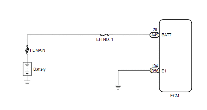
WIRING DIAGRAM
CAUTION / NOTICE / HINT
NOTICE:
Inspect the fuses for circuits related to this system before performing the following inspection procedure.
HINT:
Read freeze frame data using the Techstream. The ECM records vehicle and driving condition information as freeze frame data the moment a DTC is stored. When troubleshooting, freeze frame data can help determine if the vehicle was moving or stationary, if the engine was warmed up or not, if the air fuel ratio was lean or rich, and other data from the time the malfunction occurred.
PROCEDURE
|
1. |
CHECK HARNESS AND CONNECTOR (ECM - BATTERY) |
(a) Disconnect the cable from the negative (-) battery terminal.
(b) Disconnect the cable from the positive (+) battery terminal.
(c) Disconnect the ECM connector.
(d) Measure the resistance according to the value(s) in the table below.
Standard Resistance (Check for Open):
|
Tester Connection |
Condition |
Specified Condition |
|---|---|---|
|
A49-20 (BATT) - Battery positive (+) terminal |
Always |
Below 1 Ω |
Standard Resistance (Check for Short):
|
Tester Connection |
Condition |
Specified Condition |
|---|---|---|
|
A49-20 (BATT) or Battery positive (+) terminal - Body ground |
Always |
10 kΩ or higher |
| NG | .gif) |
REPAIR OR REPLACE HARNESS OR CONNECTOR |
|
.gif)
|
2. |
INSPECT BATTERY |
(a) Check the battery is not depleted.
OK:
Battery is not depleted.
| NG | |
CHARGE OR REPLACE BATTERY |
|
|
3. |
CHECK BATTERY TERMINAL |
(a) Check that the battery terminals are not loose or corroded.
OK:
Battery terminals are not loose or corroded.
| NG | |
REPAIR OR REPLACE BATTERY TERMINAL |
|
|
4. |
CHECK WHETHER DTC OUTPUT RECURS |
(a) Connect the Techstream to the DLC3.
(b) Turn the ignition switch to ON.
(c) Turn the Techstream on.
(d) Clear the DTCs (See page ).
(e) Turn the ignition switch off and wait for at least 30 seconds.
(f) Turn the ignition switch to ON and turn the Techstream on.
(g) Wait 5 seconds or more.
(h) Enter the following menus: Powertrain / Engine / Trouble Codes.
(i) Read the DTCs.
Result|
Result |
Proceed to |
|---|---|
|
DTC P0560 is output |
A |
|
DTC is not output |
B |
| A | |
REPLACE ECM |
| B | |
CHECK FOR INTERMITTENT PROBLEMS |
 Cold Start Ignition Timing Performance (P050B)
DESCRIPTION
This monitor will run when the engine is started at an engine coolant temperature
of -10 to 50°C (14 to 122°F). The DTC is stored after the engine idles for 13
seconds (2 trip detec ...
 Random Access Memory (RAM) (P0604)
MONITOR DESCRIPTION
The ECM continuously monitors its internal memory status. This self-check ensures
that the ECM is functioning properly. It is diagnosed by internal "mirroring" of
th ...
Other materials about Toyota Venza:
Diagnostic Trouble Code Chart
DIAGNOSTIC TROUBLE CODE CHART
Meter / Gauge System
DTC Code
Detection Item
Trouble Area
See page
B1500
Fuel Sender Open Detected
1. Harness or connector
2. Combination mete ...
Customize Parameters
CUSTOMIZE PARAMETERS
HINT:
The following items can be customized.
NOTICE:
After confirming whether the items requested by the customer are applicable
or not for customization, perform customizing operations.
Be sure to record the current se ...
Installation
INSTALLATION
PROCEDURE
1. INSTALL INSTRUMENT PANEL WIRE ASSEMBLY
(a) Connect the vent hole connector of the instrument panel wire to the
front passenger airbag assembly.
Text in Illustration
*1
Vent Hol ...

0.1214