Toyota Venza: Cold Start Ignition Timing Performance (P050B)
DESCRIPTION
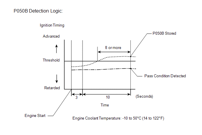
This monitor will run when the engine is started at an engine coolant temperature of -10 to 50°C (14 to 122°F). The DTC is stored after the engine idles for 13 seconds (2 trip detection logic).
The DTC is designed to monitor the ignition timing at cold start. When the engine is started at an engine coolant temperature of below 50°C (122°F), the ECM checks the ignition timing during engine idling. If the ignition timing advances beyond the specified level within 10 seconds, the ECM interprets this as a malfunction. The MIL is illuminated and a DTC is stored when the malfunction is detected in consecutive driving cycles (2 trip detection logic).
NOTICE:
The idle speed control learned values are cleared by performing a learned value reset. Idle speed control learning needs to be performed before this DTC can be stored.
|
DTC No. |
DTC Detection Condition |
Trouble Area |
|---|---|---|
|
P050B |
Insufficient ignition timing retard at cold start (2 trip detection logic). |
|
MONITOR STRATEGY
|
Related DTCs |
P050B: Cold Start Ignition Timing Performance |
|
Required Sensors/Components (Main) |
Throttle body |
|
Required Sensors/Components (Related) |
Mass air flow meter Engine coolant temperature sensor |
|
Frequency of Operation |
Once per driving cycle |
|
Duration |
10 seconds |
|
MIL Operation |
2 driving cycles |
|
Sequence of Operation |
None |
TYPICAL ENABLING CONDITIONS
|
Monitor runs whenever following DTCs not stored |
P0010 (Camshaft Timing Oil Control Valve) P0011 (VVT System - Advance) P0012 (VVT System - Retard) P0016 (VVT System - Misalignment) P0013 (Exhaust Camshaft Timing Oil Control Valve) P0014 (Exhaust VVT System - Advance) P0015 (Exhaust VVT System - Retard) P0017 (Exhaust VVT System - Misalignment) P014C, P014D, P015A, P015B, P2195, P2196, P2237, P2238, P2239, P2252, P2253 (Air Fuel Ratio Sensor) P0102, P0103 (Mass Air Flow Meter) P0115, P0117, P0118 (Engine Coolant Temperature Sensor) P0125 (Insufficient Coolant Temperature for Closed Loop Fuel Control) P0120, P0121, P0122, P0123, P0220, P0222, P0223, P2135 (Throttle Position Sensor) P0171, P0172 (Fuel System) P0300 - P0304 (Misfire) P0335 (Crankshaft Position Sensor) P0340, P0342, P0343 (Camshaft Position Sensor) P0365, P0367, P0368 (Exhaust Camshaft Position Sensor) P0351 - P0354 (Igniter) P0500 (Vehicle Speed Sensor) P0705 (Shift Lever Position Switch) P219A, P219C, P219D, P219E, P219F (Air Fuel Ratio Imbalance) |
|
Battery voltage |
8 V or higher |
|
Time after engine start |
3 seconds or more |
|
Starter |
OFF |
|
Engine coolant temperature at engine start |
-10°C (14°F) or higher |
|
Engine coolant temperature |
-10°C (14°F) or higher, and less than 50°C (122°F) |
|
Fuel-cut |
OFF |
|
Engine idling time |
3 seconds or more |
|
Vehicle speed |
Less than 3 km/h (1.875 mph) |
|
Atmospheric pressure |
76 kPa(abs) [(570 mmHg(abs)] or higher |
TYPICAL MALFUNCTION THRESHOLDS
|
Accumulated time when ignition timing retard is cut off |
8 seconds or more |
CONFIRMATION DRIVING PATTERN
- Connect the Techstream to the DLC3.
- Turn the ignition switch to ON and turn the Techstream on.
- Clear the DTCs (even if no DTCs are stored, perform the clear DTC procedure)
(See page
.gif) ).
). - Turn the ignition switch off and wait for at least 30 seconds.
- Turn the ignition switch to ON and turn the Techstream on [A].
- Enter the following menus: Powertrain / Engine / Data List / Coolant Temp.
- Check that "Coolant Temp" in the Data List are within the range of -10 to 50°C (14 to 122°F).
- Start the engine and warm it up until the coolant temperature is the same as the coolant temperature in the freeze frame data.
- Idle the engine for 1 minute or more.
- Enter the following menus: Powertrain / Engine / Trouble Codes [B].
- Read the Pending DTCs.
HINT:
- If a pending DTC is output, the system is malfunctioning.
- If a pending DTC is not output, perform the following procedure.
- Enter the following menus: Powertrain / Engine / Utility / All Readiness.
- Input the DTC: P050B.
- Check the DTC judgment result.
Techstream Display
Description
NORMAL
- DTC judgment completed
- System normal
ABNORMAL
- DTC judgment completed
- System abnormal
INCOMPLETE
- DTC judgment not completed
- Perform driving pattern after confirming DTC enabling conditions
N/A
- Unable to perform DTC judgment
- Number of DTCs which do not fulfill DTC preconditions has reached ECU memory limit
HINT:
- If the judgment result shows NORMAL, the system is normal.
- If the judgment result shows ABNORMAL, the system has a malfunction.
- If the judgment result shows INCOMPLETE or N/A, idle the engine for 3 minutes, let the engine cool down, and then perform steps [A] through [B].
- If no pending DTC is output, perform a universal trip and check for
permanent DTCs (See page ).
HINT:
- If a permanent DTC is output, the system is malfunctioning.
- If no permanent DTC is output, the system is normal.
WIRING DIAGRAM
Refer to DTC P0102 (See page ).
CAUTION / NOTICE / HINT
HINT:
- DTC P050B may be output when the engine has the symptoms listed below.
If necessary, check the trouble areas listed below.
Symptom
Factor
Trouble Area
Low idle speed when engine is cold (immediately after engine start)
Excessive engine friction
- Engine oil deterioration
- Drive belt tension
- A/C compressor
- Generator
Rough idle when engine is cold (immediately after engine start)
Abnormal combustion
Fuel quality
- Read freeze frame data using the Techstream. The ECM records vehicle and driving condition information as freeze frame data the moment a DTC is stored. When troubleshooting, freeze frame data can help determine if the vehicle was moving or stationary, if the engine was warmed up or not, if the air fuel ratio was lean or rich, and other data from the time the malfunction occurred.
PROCEDURE
|
1. |
CHECK ANY OTHER DTCS OUTPUT (IN ADDITION TO DTC P050B) |
(a) Connect Techstream to the DLC3.
(b) Turn the ignition switch to ON.
(c) Turn the Techstream on.
(d) Enter the following the menus: Powertrain / Engine / Trouble Codes.
(e) Read the DTCs.
|
Result |
Proceed to |
|---|---|
|
DTC P050B is output |
A |
|
DTC P050B and other DTCs are output |
B |
HINT:
If any DTCs other than P050B are output, troubleshoot those DTCs first.
| B | .gif) |
GO TO DTC CHART |
|
.gif)
|
2. |
READ VALUE USING TECHSTREAM (FUEL TRIM) |
HINT:
Calculate the total fuel trim values to check the characteristic deviation of the mass air flow meter.
(a) Connect the Techstream to the DLC3.
(b) Start the engine.
(c) Turn the Techstream on.
(d) Enter the following menus: Powertrain / Engine / Data List / Short FT #1 and Long FT #1.
(e) Read the values displayed on the Techstream at engine idle.
(f) Add together the Short FT #1 and Long FT #1 values to obtain the total fuel trim.
OK:
Total of Short FT #1 and Long FT #1 values is between -20% and 20%.
| NG | |
GO TO STEP 5 |
|
|
3. |
INSPECT THROTTLE BODY ASSEMBLY |
(a) Check for deposits around the throttle valve and throttle valve condition.
OK:
No deposits around throttle valve and throttle valve moves smoothly.
| OK | |
GO TO STEP 15 |
|
|
4. |
REPAIR OR REPLACE THROTTLE BODY ASSEMBLY |
(a) Repair or replace the throttle body assembly (See page
).
HINT:
Perform "Inspection After Repair" after repairing or replacing the throttle body
(See page ).
| NEXT | |
GO TO STEP 14 |
|
5. |
CHECK PCV SYSTEM |
(a) Check the PCV hose connections (See page
).
OK:
PCV hose is connected correctly and is not damaged.
| NG | |
GO TO STEP 10 |
|
|
6. |
CHECK INTAKE SYSTEM |
(a) Check the intake system for vacuum leaks (See page
).
OK:
No leakage from intake system.
| NG | |
GO TO STEP 11 |
|
|
7. |
CHECK AIR CLEANER FILTER ELEMENT SUB-ASSEMBLY |
(a) Visually check that the air cleaner filter element is not excessively contaminated with dirt or oil.
OK:
Air cleaner filter element is not excessively contaminated with dirt or oil.
| NG | |
GO TO STEP 12 |
|
|
8. |
PERFORM ACTIVE TEST USING TECHSTREAM (CONTROL THE VVT LINEAR) |
(a) Operate the VVT system through the Active test, and check if the VVT system is operating normally.
(1) Perform the Active Test, referring to DTC P0011 Inspection Procedure (VVT
system for intake camshaft) (See page ).
(2) Perform the Active Test, referring to DTC P0014 Inspection Procedure (VVT
system for exhaust camshaft) (See page ).
| NG | |
GO TO STEP 13 |
|
|
9. |
READ VALUE USING TECHSTREAM (MAF) |
| OK | |
GO TO STEP 15 |
| NG | |
GO TO STEP 16 |
|
10. |
REPAIR OR REPLACE PCV HOSE |
(a) Repair or replace the PCV hose.
| NEXT | |
GO TO STEP 14 |
|
11. |
REPAIR OR REPLACE INTAKE SYSTEM |
(a) Repair or replace the intake system.
HINT:
Perform "Inspection After Repair" after repairing or replacing the intake system
(See page ).
| NEXT | |
GO TO STEP 14 |
|
12. |
REPLACE AIR CLEANER FILTER ELEMENT SUB-ASSEMBLY |
(a) Replace the air cleaner filter element sub-assembly.
| NEXT | |
GO TO STEP 14 |
|
13. |
CHECK AND REPAIR VVT SYSTEM |
(a) Check and repair the VVT system.
HINT:
- Refer to DTC P0011 Inspection Procedure for intake camshaft (See page
).
- Refer to DTC P0014 Inspection Procedure for exhaust camshaft (See page
).
|
|
14. |
CHECK WHETHER DTC OUTPUT RECURS (DTC P050B) |
NOTICE:
In this operation, the engine must be cold (the same level as the engine coolant temperature recorded in the freeze frame data).
(a) Connect the Techstream to the DLC3.
(b) Turn the ignition switch to ON.
(c) Turn the Techstream on.
(d) Clear the DTCs (See page ).
(e) Turn the ignition switch off and wait for at least 30 seconds.
(f) Turn the ignition switch to ON and turn the Techstream on.
(g) Enter the following menus: Powertrain / Engine / Data List / Coolant Temp.
(h) Check that the engine coolant temperature is between -10 and 50°C (14 and 122°F)
(i) Start the engine and warm it up.
(j) Drive the vehicle in accordance with the driving pattern described in the Confirmation Driving Pattern.
(k) Enter the following menus: Powertrain / Engine / Utility / All Readiness.
(l) Input the DTC: P050B.
(m) Check the DTC judgment result.
|
Result |
Proceed to |
|---|---|
|
NORMAL (DTC is not output) |
A |
|
ABNORMAL (DTC P050B is output) |
B |
| A | |
END |
| B | |
GO TO STEP 16 |
|
15. |
CHECK WHETHER DTC OUTPUT RECURS (DTC P050B) |
NOTICE:
In this operation, the engine must be cold (the same level as the engine coolant temperature recorded in the freeze frame data).
(a) Connect the Techstream to the DLC3.
(b) Turn the ignition switch to ON.
(c) Turn the Techstream on.
(d) Clear the DTCs (See page ).
(e) Turn the ignition switch off and wait for at least 30 seconds.
(f) Turn the ignition switch to ON and turn the Techstream on.
(g) Enter the following menus: Powertrain / Engine / Data List / Coolant Temp.
(h) Check that the engine coolant temperature is between -10 and 50°C (14 and 122°F)
(i) Start the engine and warm it up.
(j) Drive the vehicle in accordance with the driving pattern described in the Confirmation Driving Pattern.
(k) Enter the following menus: Powertrain / Engine / Utility / All Readiness.
(l) Input the DTC: P050B.
(m) Check the DTC judgment result.
|
Result |
Proceed to |
|---|---|
|
NORMAL (DTC is not output) |
A |
|
ABNORMAL (DTC P050B is output) |
B |
| A | |
CHECK FOR INTERMITTENT PROBLEMS |
|
|
16. |
CHECK HARNESS AND CONNECTOR (MASS AIR FLOW METER CONNECTOR CONNECTION) |
(a) Check the connection and terminal contact pressure of connectors and wire
harnesses between the mass air flow meter and ECM (See page
).
HINT:
Repair any problems.
|
|
17. |
CHECK WHETHER DTC OUTPUT RECURS |
NOTICE:
In this operation, the engine must be cold (approximately the same as the engine coolant temperature recorded in the freeze frame data).
(a) Connect the Techstream to the DLC3.
(b) Turn the ignition switch to ON.
(c) Turn the Techstream on.
(d) Clear the DTCs (See page ).
(e) Turn the ignition switch off and wait for at least 30 seconds.
(f) Turn the ignition switch to ON and turn the Techstream on.
(g) Enter the following menus: Powertrain / Engine / Data List / Coolant Temp.
(h) Check that the engine coolant temperature is between -10 and 50°C (14 and 122°F)
(i) Start the engine and warm it up.
(j) Drive the vehicle in accordance with the driving pattern described in Confirmation Driving Pattern.
(k) Enter the following menus: Powertrain / Engine / Utility / All Readiness.
(l) Input the DTC: P050B.
(m) Check the DTC judgment result.
|
Result |
Proceed to |
|---|---|
|
ABNORMAL (DTC P050B is output) |
A |
|
NORMAL (DTC is not output) |
B |
| B | |
END |
|
|
18. |
CHECK HARNESS AND CONNECTOR (MASS AIR FLOW METER - ECM) |
| NG | |
REPAIR OR REPLACE HARNESS OR CONNECTOR |
|
|
19. |
REPLACE MASS AIR FLOW METER |
(a) Replace the mass air flow meter (See page
).
HINT:
- If the result of the inspection performed in step 9 indicated no problem, proceed to the next step without replacing the mass air flow meter.
- Perform "Inspection After Repair" after replacing the mass air flow
meter (See page ).
|
|
20. |
CONFIRM WHETHER MALFUNCTION HAS BEEN SUCCESSFULLY REPAIRED |
NOTICE:
In this operation, the engine must be cold (approximately the same as the engine coolant temperature recorded in the freeze frame data).
(a) Connect the Techstream to the DLC3.
(b) Turn the ignition switch to ON.
(c) Turn the Techstream on.
(d) Clear the DTCs (See page ).
(e) Turn the ignition switch off and wait for at least 30 seconds.
(f) Turn the ignition switch to ON and turn the Techstream on.
(g) Enter the following menus: Powertrain / Engine / Data List / Coolant Temp.
(h) Check that the engine coolant temperature is between -10 and 50°C (14 and 122°F).
(i) Start the engine and warm it up.
(j) Drive the vehicle in accordance with the driving pattern described in Confirmation Driving Pattern.
(k) Enter the following menus: Powertrain / Engine / Utility / All Readiness.
(l) Input the DTC: P050B.
(m) Check the DTC judgment result.
|
Result |
Proceed to |
|---|---|
|
NORMAL (DTC is not output) |
A |
|
ABNORMAL (DTC P050B is output) |
B |
| A | |
END |
| B | |
REPLACE ECM |
 Cold Start Idle Air Control System Performance (P050A)
MONITOR DESCRIPTION
This monitor will run when the engine is started at an engine coolant temperature
of -10 to 50°C (14 to 122°F). The DTC is stored after the engine idles for 13
seconds (2 tr ...
 System Voltage (P0560)
DESCRIPTION
The battery supplies electricity to the ECM even when the ignition switch is
off. This power allows the ECM to store data such as DTC history, freeze frame data
and fuel trim values. ...
Other materials about Toyota Venza:
Customize Parameters
CUSTOMIZE PARAMETERS
1. CUSTOMIZING FUNCTION WITH TECHSTREAM
HINT:
The items in the table below can be customized.
NOTICE:
When the customer requests a change in a function, first make sure that
the function can be customized.
Be sure to m ...
Disassembly
DISASSEMBLY
CAUTION / NOTICE / HINT
HINT:
Use the same procedure for the RH side and the LH side.
The procedure listed below is for the LH side.
PROCEDURE
1. REMOVE REAR WHEEL
2. REMOVE REAR AXLE SHAFT NUT (for AWD)
NOTICE:
Perform th ...
Engine (ignition) switch (vehicles with smart key system)
Performing the following operations when carrying the electronic key on your
person starts the engine or changes “ENGINE START STOP” switch modes.
- Starting the engine
Check that the parking brake is set.
Check that the shift lever is set
i ...

0.1885