Toyota Venza: System Diagram
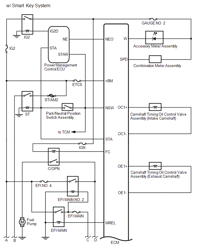
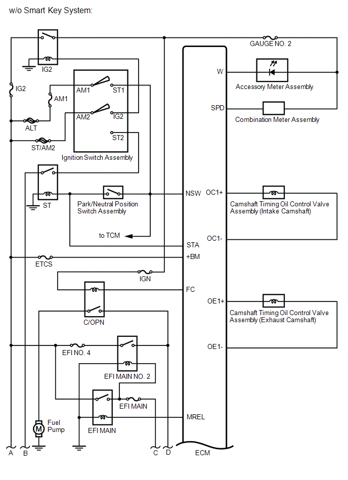
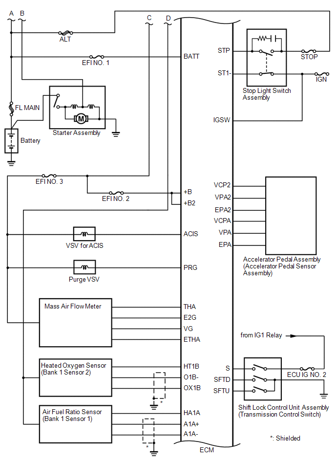
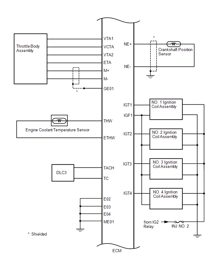
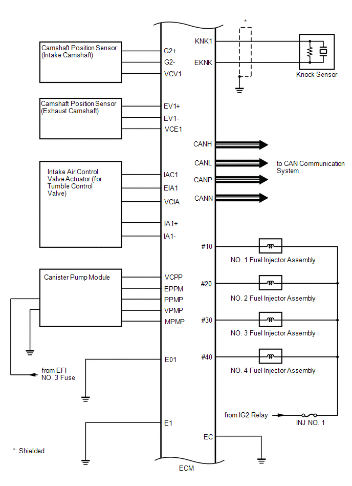
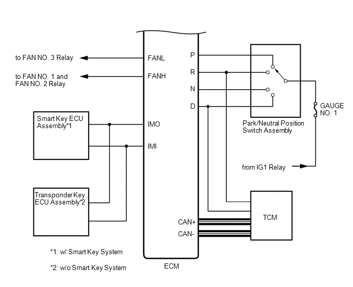
SYSTEM DIAGRAM
 How To Proceed With Troubleshooting
CAUTION / NOTICE / HINT
HINT:
*: Use the Techstream.
PROCEDURE
1.
VEHICLE BROUGHT TO WORKSHOP
NEXT
...
 Basic Inspection
BASIC INSPECTION
When the malfunction is not confirmed by the DTC check, troubleshooting should
be carried out in all circuits considered to be possible causes of the problem.
In many cases, by c ...
Other materials about Toyota Venza:
Operation Check
OPERATION CHECK
1. AUTOMATIC LIGHT CONTROL SYSTEM OPERATION CHECK
(a) Turn the ignition switch to ON.
(b) Turn the light control switch to the AUTO position.
(c) Cover the automatic light control sensor.
(d) Check that the taillights and low beam headligh ...
Back Door Support
Components
COMPONENTS
ILLUSTRATION
Removal
REMOVAL
PROCEDURE
1. REMOVE BACK DOOR STAY ASSEMBLY
NOTICE:
Avoid touching the piston rod as much as possible to prevent foreign
matter from attaching to it. Be sure to hold the cylinder whil ...
Reassembly
REASSEMBLY
PROCEDURE
1. INSTALL REAR DRIVE SHAFT DUST COVER
(a) Using SST and a steel plate, install a new rear drive shaft dust
cover to the rear drive shaft inboard joint assembly.
Text in Illustration
*1
...

0.1669