Toyota Venza: Oil Pressure Switch
Components
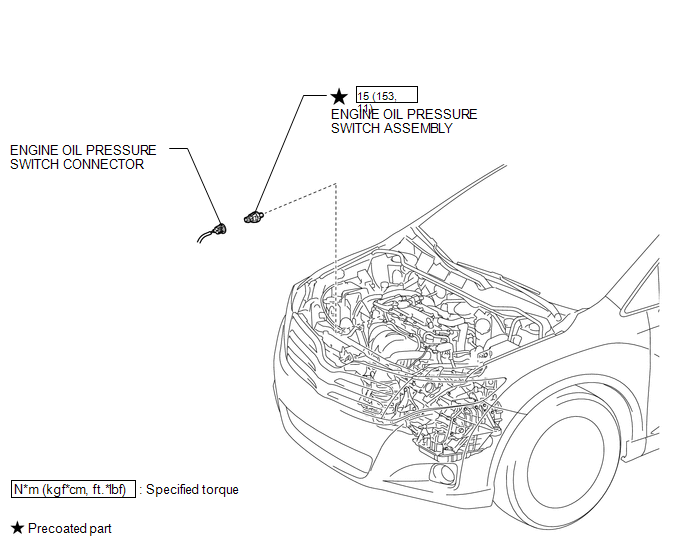
COMPONENTS
ILLUSTRATION
Inspection
INSPECTION
PROCEDURE
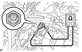
1. INSPECT ENGINE OIL PRESSURE SWITCH ASSEMBLY
(a) Disconnect the oil pressure switch connector.
(b) Start the engine.
|
(c) Measure the resistance according to the value(s) in the table below. Standard Resistance:
If the result is not as specified, replace the oil pressure switch assembly. |
|
Removal
REMOVAL
PROCEDURE
1. REMOVE ENGINE OIL PRESSURE SWITCH ASSEMBLY
|
(a) Disconnect the oil pressure switch connector. |
|
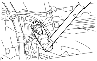
(b) Using a 24 mm deep socket wrench, remove the oil pressure switch.
Installation
INSTALLATION
PROCEDURE
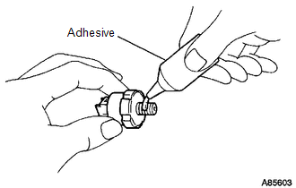
1. INSTALL ENGINE OIL PRESSURE SWITCH ASSEMBLY
|
(a) Apply adhesive to 2 or 3 threads of the oil pressure switch. Adhesive: TOYOTA Genuine Adhesive 1344, Three Bond 1344 or equivalent. NOTICE: Do not let adhesive adhere to the oil hole. |
|
|
(b) Using a 24 mm deep socket wrench, install the oil pressure switch. Torque: 15 N·m {153 kgf·cm, 11 ft·lbf} NOTICE: Do not start the engine within 1 hour of installation. |
|
.png)
(c) Connect the oil pressure switch connector.
2. INSPECT FOR OIL LEAK
.gif)
3. INSPECT ENGINE OIL LEVEL
 Replacement
REPLACEMENT
CAUTION / NOTICE / HINT
CAUTION:
Prolonged and repeated contact with engine oil will result in the removal
of natural oils from the skin, leading to dryness, irritation and ...
 Oil Pump
...
Other materials about Toyota Venza:
How To Proceed With Troubleshooting
CAUTION / NOTICE / HINT
HINT:
Use the following procedure to troubleshoot the window defogger system.
*: Use the Techstream.
PROCEDURE
1.
VEHICLE BROUGHT TO WORKSHOP
NEXT
...
Removal
REMOVAL
PROCEDURE
1. ALIGN FRONT WHEELS FACING STRAIGHT AHEAD
2. DISCONNECT CABLE FROM NEGATIVE BATTERY TERMINAL
CAUTION:
Wait at least 90 seconds after disconnecting the cable from the negative (-)
battery terminal to disable the SRS system.
NOTICE:
...
BUS IC Communication Malfunction (B1497/97)
DESCRIPTION
The air conditioning harness connects the A/C amplifier and each servo. The A/C
amplifier supplies power and sends operation instructions to each servo through
the air conditioning harness. Each servo sends the damper position information to
...

0.125