Toyota Venza: System Diagram
SYSTEM DIAGRAM
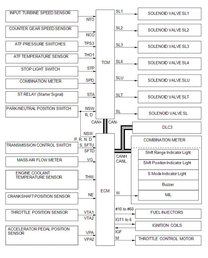
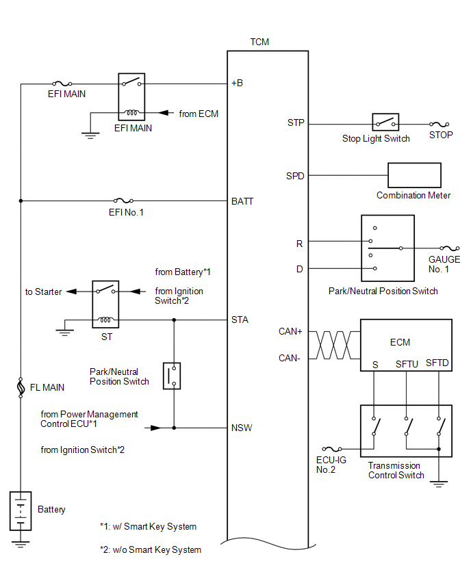
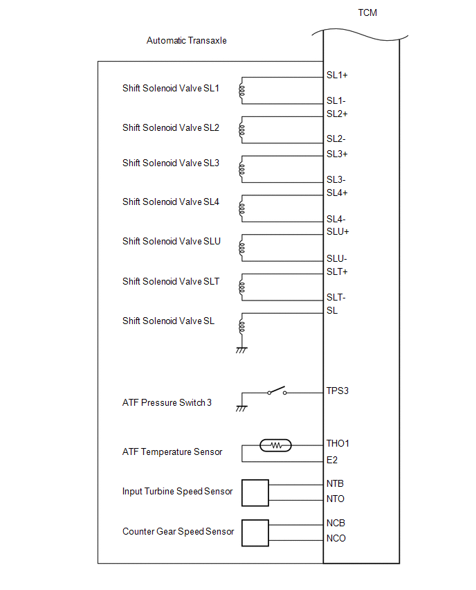
The configuration of the electronic control system in the U660E automatic transaxle is as shown in the following chart.
 System Description
SYSTEM DESCRIPTION
1. SYSTEM DESCRIPTION
(a) The Electronic Controlled Automatic Transaxle (ECT) is an automatic transaxle
that has its shift timing electronically controlled by the Transmission C ...
 How To Proceed With Troubleshooting
CAUTION / NOTICE / HINT
HINT:
The TCM of this system is connected to the CAN communication system.
Therefore, before starting troubleshooting, make sure to check that there
is no tro ...
Other materials about Toyota Venza:
Driver Side Power Window Auto Up / Down Function does not Operate with Power
Window Master Switch
DESCRIPTION
If the manual up/down function can be performed but the auto up/down function
cannot, then the fail-safe mode may be functioning.
If the power window initialization (See page
) has not been performed, the auto up/down function
will not oper ...
Data List / Active Test
DATA LIST / ACTIVE TEST
1. DATA LIST
HINT:
Using the Techstream to read the Data List allows the values or states of switches,
sensors, actuators and other items to be read without removing any parts. This non-intrusive
inspection can be very useful bec ...
Seat Position Sensor
Components
COMPONENTS
ILLUSTRATION
On-vehicle Inspection
ON-VEHICLE INSPECTION
CAUTION / NOTICE / HINT
CAUTION:
Be sure to follow the correct removal and installation procedures of the seat
position sensor.
PROCEDURE
1. INSPECT SEAT POSITION S ...

0.1187