Toyota Venza: Reassembly
REASSEMBLY
PROCEDURE
1. INSTALL NO. 2 STEERING RACK BOOT
|
(a) Apply lithium soap base glycol grease to the inside of the small opening of a new No. 2 steering rack boot. |
|
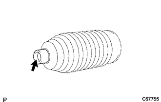
(b) Install the No. 2 steering rack boot to the groove on the rack housing.
NOTICE:
- Be careful not to damage or twist the boot.
- Make sure that the boot is free of rust and foreign matter.
2. INSTALL NO. 1 STEERING RACK BOOT
HINT:
Perform the same procedure as for the No. 2 steering rack boot.
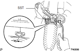
3. INSTALL NO. 2 STEERING RACK BOOT CLAMP
|
(a) Using SST, tighten a new No. 2 steering rack boot clamp as shown in the illustration. SST: 09521-24010 Clearance: 3.0 mm (0.118 in.) or less NOTICE: Be careful not to damage or twist the boot. |
|
4. INSTALL NO. 1 STEERING RACK BOOT CLAMP
HINT:
Perform the same procedure as for the No. 2 steering rack boot clamp.
SST: 09521-24010
5. INSTALL STEERING RACK BOOT CLIP (for LH Side)
(a) Using pliers, install the steering rack boot clip.
6. INSTALL STEERING RACK BOOT CLIP (for RH Side)
HINT:
Perform the same procedure as for the LH side.
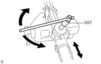
7. INSPECT STEERING GEAR ASSEMBLY
|
(a) Using SST, rotate the pinion shaft to see if both the left and the right steering rack boots expand and contract smoothly. SST: 09616-00020 HINT: If the operation cannot be done as specified, use new steering rack boot clamps and reinstall the steering rack boots. |
|
 Installation
INSTALLATION
CAUTION / NOTICE / HINT
NOTICE:
When disconnecting the steering intermediate shaft assembly and pinion shaft
of steering gear assembly, be sure to place matchmarks before servicing.
...

Other materials about Toyota Venza:
Freeze Frame Data
FREEZE FRAME DATA
1. CHECK FREEZE FRAME DATA
(a) Connect the Techstream to the DLC3.
(b) Turn the ignition switch to ON.
(c) Turn the Techstream on.
(d) Enter the following menus: Body Electrical / Navigation System / Trouble
Codes.
(e) Select a DTC to ...
Lost Communication with ECM (U0101,U0073,U0126,U0129,U0142,U0182,U1000)
DESCRIPTION
The DTCs are stored when the CAN communication system is malfunctioning.
DTC No.
DTC Detection Condition
Trouble Area
U0101
Lost communication with ECM
CAN communication syst ...
Rear Occupant Classification Sensor RH Circuit Malfunction (B1783)
DESCRIPTION
The rear occupant classification sensor RH circuit consists of the occupant classification
ECU and rear occupant classification sensor RH.
DTC B1783 is recorded when a malfunction is detected in the rear occupant classification
sensor RH circ ...

0.117