Toyota Venza: Disassembly
DISASSEMBLY
PROCEDURE
1. REMOVE TRANSPONDER KEY ECU ASSEMBLY (w/ Engine Immobiliser System)
.gif)
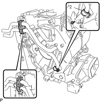
2. REMOVE NO. 1 FINISH PANEL MOUNTING BRACKET
|
(a) Remove the 2 bolts and 2 No. 1 finish panel mounting brackets as shown in the illustration. |
|
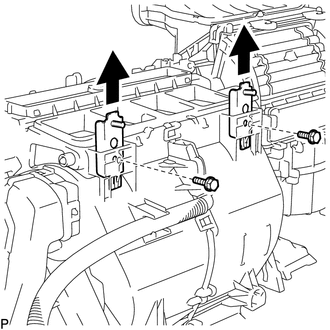
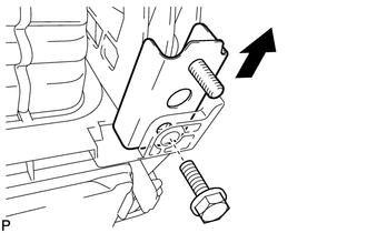
3. REMOVE NO. 2 FINISH PANEL MOUNTING BRACKET
|
(a) Remove the bolt and No. 2 finish panel mounting bracket as shown in the illustration. |
|
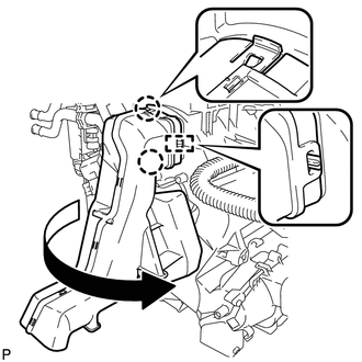
4. REMOVE NO. 3 AIR DUCT SUB-ASSEMBLY
|
(a) Disengage the 2 claws and guide, and remove the No. 3 air duct sub-assembly as shown in the illustration. |
|
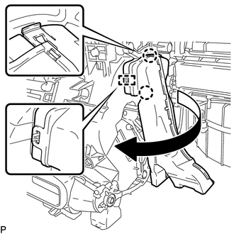
5. REMOVE NO. 2 AIR DUCT SUB-ASSEMBLY
|
(a) Disengage the 2 claws and guide, and remove the No. 2 air duct sub-assembly as shown in the illustration. |
|
6. REMOVE AIR CONDITIONING HARNESS ASSEMBLY
(a) Disconnect each connector.
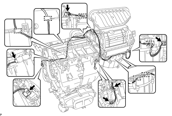
(b) Disengage each clamp and remove the air conditioning harness assembly.
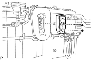
7. REMOVE COOLER EXPANSION VALVE
|
(a) Using a 4 mm hexagon wrench, remove the 2 hexagon bolts and cooler expansion valve. |
|
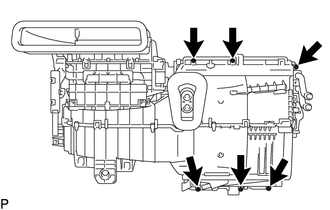
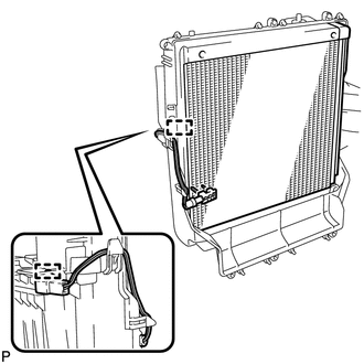
8. REMOVE AIR CONDITIONING RADIATOR ASSEMBLY
|
(a) Remove the 6 screws. |
|
|
(b) Disengage the guide and disconnect the wire harness. |
|
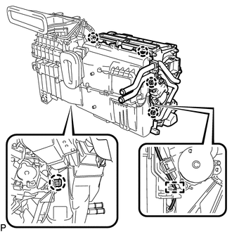
(c) Disengage the 5 claws and remove the air conditioning radiator assembly from the blower assembly with cooler evaporator sub-assembly.
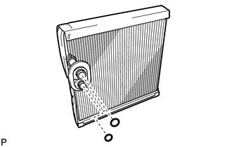
9. REMOVE COOLER EVAPORATOR SUB-ASSEMBLY
|
(a) Disengage the clamp and remove the cooler evaporator sub-assembly with the No. 1 cooler thermistor. |
|
|
(b) Remove the 2 O-rings from the cooler evaporator sub-assembly. |
|
10. REMOVE NO. 1 COOLER THERMISTOR
11. REMOVE ASPIRATOR PIPE
|
(a) Disengage the clamp. |
|
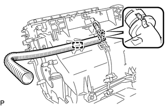
(b) Disengage the 2 claws and remove the aspirator pipe.
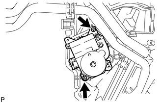
12. REMOVE AIR MIX CONTROL SERVO MOTOR SUB-ASSEMBLY
|
(a) Remove the 2 screws and air mix control servo motor sub-assembly. |
|
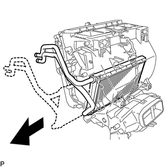
13. REMOVE HEATER RADIATOR UNIT SUB-ASSEMBLY
|
(a) Disengage the 3 claws and remove the heater clamp. Text in Illustration
|
|
(b) Remove the screw and clamp.
|
(c) Remove the heater radiator unit sub-assembly as shown in the illustration. NOTICE: Prepare a drain pan or cloth in case the cooling water leaks. |
|
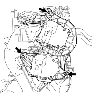
14. REMOVE AIR OUTLET CONTROL SERVO MOTOR SUB-ASSEMBLY
|
(a) Remove the 3 screws and air outlet control servo motor sub-assembly. |
|
 Removal
REMOVAL
CAUTION / NOTICE / HINT
NOTICE:
Make sure to select FACE mode before disconnecting the cable from the negative
(-) battery terminal.
PROCEDURE
1. RECOVER REFRIGERANT FROM REFRIGERATION ...
 Reassembly
REASSEMBLY
PROCEDURE
1. INSTALL AIR OUTLET CONTROL SERVO MOTOR SUB-ASSEMBLY
(a) Check that the slots, links and gears of the air outlet control servo
motor sub-assembly are positione ...
Other materials about Toyota Venza:
Front Passenger Side Power Mirror cannot be Adjusted with Power Mirror Switch
SYSTEM DESCRIPTION
When the mirror adjust switch is operated, the main body ECU (driver side junction
block assembly) detects the switch operation and sends the mirror adjust switch
signal to the outer mirror control ECU assembly (front passenger door) vi ...
Dtc Check / Clear
DTC CHECK / CLEAR
HINT:
Use the Techstream to read and clear the DTC of the occupant classification ECU,
otherwise the DTCs cannot be read and cleared.
1. DTC CHECK
(a) Turn the ignition switch off.
(b) Connect the Techstream to the DLC3.
(c) Turn the ...
ECU Version Miss Match (C1288/88)
DESCRIPTION
DTC Code
DTC Detection Condition
Trouble Area
C1288/88
ECM does not match.
ECM
PROCEDURE
1.
CHECK CAN COMMUNICATION SYSTEM
(a) Chec ...

0.1319