Toyota Venza: System Diagram
SYSTEM DIAGRAM
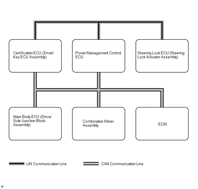
 Communication Table
|
Transmitting ECU (Transmitter) |
Receiving ECU |
Signal |
Communication Method |
|---|---|---|---|
|
Main body ECU (Driver side junction block assembly) |
Certification ECU (Smart key ECU assembly) |
Courtesy light switch signal |
CAN |
|
Door lock output signal |
|||
|
Back door output request signal |
|||
|
Door lock position switch signal |
|||
|
Driver door key operated switch signal |
|||
|
Certification ECU (Smart key ECU assembly) |
Main body ECU (Driver side junction block assembly) |
Illumination light request signal |
CAN |
|
Door lock/unlock request signal |
|||
|
Certification ECU (Smart key ECU assembly) |
Combination meter assembly |
Meter buzzer single tone request signal |
CAN |
|
Meter buzzer intermittent tone request signal |
|||
|
Meter buzzer continuous tone request signal |
|||
|
Key loss warning signal |
|||
|
Low key battery warning signal |
|||
|
Steering lock malfunction warning signal |
|||
|
Steering lock not-released warning signal |
|||
|
Shift position warning signal |
|||
|
Emergency operation support display request signal |
|||
|
Engine start method display request signal |
|||
|
Combination meter assembly |
|
Vehicle speed signal |
CAN |
|
Steering lock ECU (Steering lock actuator assembly) |
Certification ECU (Smart key ECU assembly) |
Encryption code signal |
LIN |
|
Encryption code finish signal |
|||
|
Encryption calculate fixed number memory requirement signal |
|||
|
During entry control signal |
 Parts Location
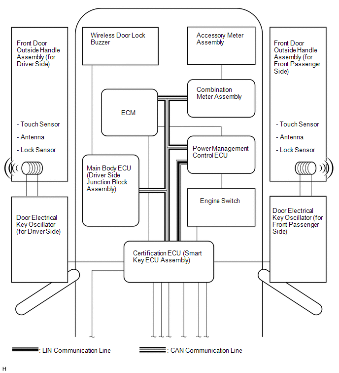
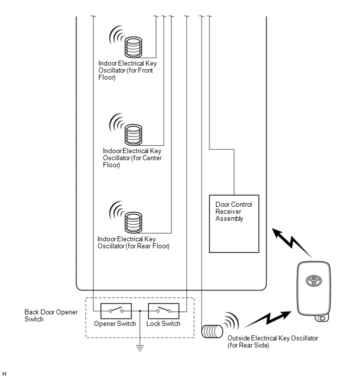
PARTS LOCATION
ILLUSTRATION
ILLUSTRATION
ILLUSTRATION
ILLUSTRATION
...
 System Description
SYSTEM DESCRIPTION
CAUTION:
If using a pacemaker, be sure to read the manual of the pacemaker before using
the key, as the radio waves of the key may affect the pacemaker.
1. SMART KEY SYSTEM DES ...
Other materials about Toyota Venza:
Driver Side Door Entry Lock Function does not Operate
DESCRIPTION
If the driver door entry unlock function operates normally, but its entry lock
function does not, this means that the request code from the driver door is being
output normally. In this case, a malfunction in the lock sensor circuit (from the ...
Rear window defogger
Clear the rear window using the defogger.
On/off
The defogger will automatically turn off after 15 or 60 minutes.
This operation time changes according to the ambient temperature and vehicle
speed.
Pressing the switch again also turns the defogger off. ...
Steering Lock Motor Drive Power Circuit
DESCRIPTION
The steering lock ECU (steering lock actuator assembly) is connected to the power
management control ECU. The steering lock ECU (steering lock actuator assembly)
cannot activate the motor unless it receives permission signals from both ECUs.
...

0.1791