Toyota Venza: Reassembly
REASSEMBLY
PROCEDURE
1. INSTALL REAR CONSOLE ARMREST ASSEMBLY
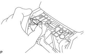
(a) Temporarily install the rear console armrest assembly.
|
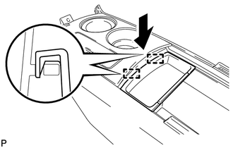
(b) Push in the box door hinge shafts by hand as far as possible. HINT:
|
|
|
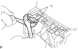
(c) Using pliers, push in the box door hinge shafts completely. Text in Illustration
HINT:
|
|
|
(d) Install the rear console armrest assembly with the 2 E-rings. |
|
.png)
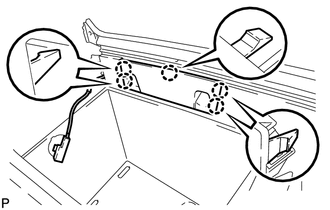
2. INSTALL REAR CONSOLE END PANEL SUB-ASSEMBLY
|
(a) Engage the 4 clips to install the rear console end panel sub-assembly. |
|
.png)
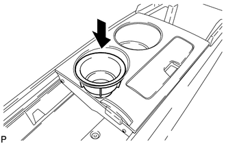
3. INSTALL CENTER POWER OUTLET SOCKET COVER
.gif)
4. INSTALL CENTER POWER POINT SOCKET ASSEMBLY
5. INSTALL CONSOLE BOX ILLUMINATION LIGHT ASSEMBLY
6. INSTALL CONSOLE BOX WIRE
|
(a) Connect the connectors to install the console box wire. |
|
.png)
7. INSTALL CONSOLE MOUNTING RETAINER ASSEMBLY
|
(a) Engage the 5 claws to install the console mounting retainer assembly. |
|
8. INSTALL NO. 2 CONSOLE BOX DUCT
|
(a) Install the No. 2 console box duct with the 2 screws. |
|
.png)
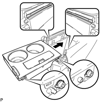
9. INSTALL REAR CONSOLE UPPER PANEL SUB-ASSEMBLY
|
(a) Aligning the inside groove of the front console box assembly with the rear console upper panel hinge, slide the rear console upper panel sub-assembly and install it. |
|
10. INSTALL STEREO JACK ADAPTER ASSEMBLY
11. INSTALL FRONT CONSOLE BOX COVER
|
(a) Engage the 2 claws. |
|
.png)
(b) Install the front console box cover with the 3 screws.
(c) Engage the clamp.
12. INSTALL CONSOLE BOX POCKET
|
(a) Engage the 2 guides to install the console box pocket. |
|
13. INSTALL INSTRUMENT PANEL CUP HOLDER DAMPER
|
(a) Install the instrument panel cup holder damper. |
|
14. INSTALL NO. 1 CONSOLE BOX CARPET
|
(a) Install the No. 1 console box carpet. |
|
.png)
 Installation
INSTALLATION
PROCEDURE
1. INSTALL CONSOLE BOX ASSEMBLY
(a) Connect the connectors.
(b) Engage the 2 claws.
(c) Install the scr ...

Other materials about Toyota Venza:
Adjustment
ADJUSTMENT
PROCEDURE
1. ADJUST STEERING WHEEL OFF CENTER
(a) Inspect steering wheel off center.
(1) Apply masking tape on the top center of the steering wheel and steering
column upper cover.
Text in Illustration
*1
...
Tire information
Typical tire symbols
►Standard tire
►Compact spare tire
1. Tire size
2. DOT and Tire Identification Number (TIN)
3. Location of treadwear indicators
4. Tire ply composition and materials Plies are layers of rubber-coated parallel
cords ...
Removal
REMOVAL
PROCEDURE
1. REMOVE REAR DOOR SCUFF PLATE LH
2. REMOVE REAR DOOR OPENING TRIM WEATHERSTRIP LH
3. REMOVE TONNEAU COVER ASSEMBLY (w/ Tonneau Cover)
4. REMOVE DECK BOARD ASSEMBLY
5. REMOVE NO. 3 DECK BOARD SUB-ASSEMBLY
6. REMOVE DECK ...

0.1157