Toyota Venza: Parts Location
PARTS LOCATION
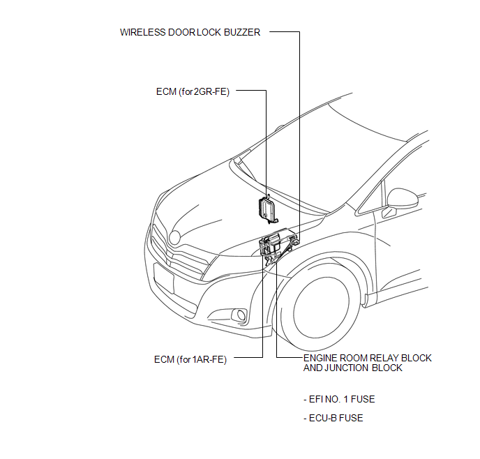
ILLUSTRATION
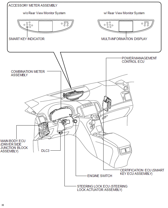
ILLUSTRATION
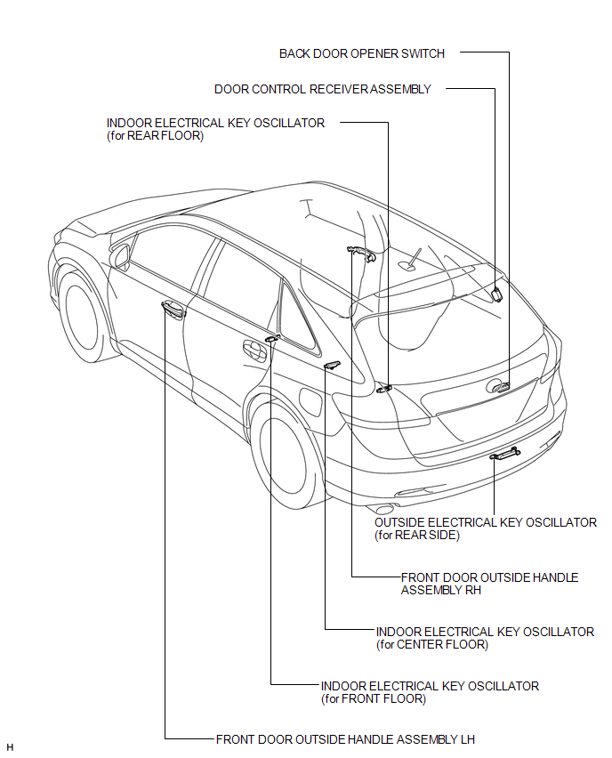
ILLUSTRATION
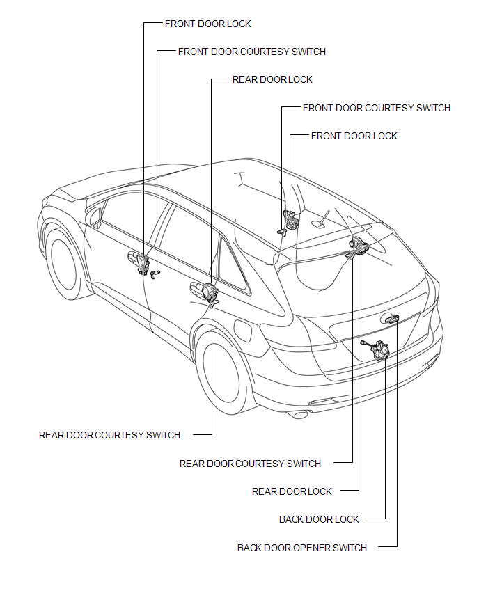
ILLUSTRATION
 Precaution
PRECAUTION
1. PRECAUTION FOR DISCONNECTING CABLE FROM NEGATIVE BATTERY TERMINAL
NOTICE:
When disconnecting the cable from the negative (-) battery terminal, initialize
the following system after ...
 System Diagram
SYSTEM DIAGRAM
Communication Table
Transmitting ECU (Transmitter)
Receiving ECU
Signal
Communication Method
Main body ECU (Driver si ...
Other materials about Toyota Venza:
On-vehicle Inspection
ON-VEHICLE INSPECTION
PROCEDURE
1. CHECK BATTERY CONDITION
NOTICE:
If the battery is weak or if the engine is difficult to start, perform the following
procedure.
(a) Check the battery for damage or deformation. If severe damage, deformation
or leakag ...
Outer Rear View Mirror Glass
Components
COMPONENTS
ILLUSTRATION
Inspection
INSPECTION
PROCEDURE
1. INSPECT OUTER MIRROR RH
(a) Check the outer mirror heater operation.
(1) Measure the resistance according to the value(s) in the table below.
Standard Resistanc ...
Installation
INSTALLATION
PROCEDURE
1. TEMPORARILY INSTALL REAR STABILIZER BAR BRACKET LH (for Front Side)
(a) Temporarily install the rear stabilizer bar bracket LH (front side)
with the bolt.
HINT:
Loosely tighten the bolt so that the bracket can ...

0.1297