Toyota Venza: Fuel Sender Open Detected (B1500)
DESCRIPTION
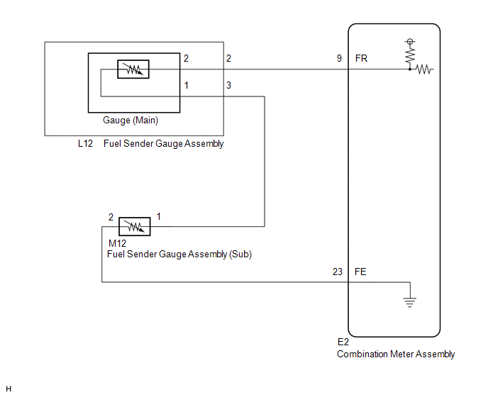
This DTC is output when the combination meter assembly detects a fuel sender gauge malfunction via the direct line.
|
DTC No. |
DTC Detection Condition |
Trouble Area |
|---|---|---|
|
B1500 |
When either of the following conditions is detected:
|
|
WIRING DIAGRAM
PROCEDURE
|
1. |
READ VALUE USING TECHSTREAM (FUEL INPUT) |
(a) Connect the Techstream to the DLC3.
(b) Turn the ignition switch to ON.
(c) Turn the Techstream on.
(d) Enter following menus: Body Electrical / Combination Meter / Data List.
(e) Check the values by referring to the table below.
Combination Meter|
Tester Display |
Measurement Item/Range |
Normal Condition |
Diagnostic Note |
|---|---|---|---|
|
Fuel Input |
Fuel input signal/Min.: 0, Max.: 127.5 |
The current fuel level displayed |
Unit: Liter |
|
Result |
Proceed to |
|---|---|
|
Fuel level data can be displayed on the Techstream and DTC B1500 is output. |
A |
|
Fuel level data cannot be displayed on the Techstream. |
B |
| A | .gif) |
REPLACE COMBINATION METER ASSEMBLY |
|
.gif)
|
2. |
INSPECT COMBINATION METER ASSEMBLY |
|
(a) Disconnect the E2 connector. |
|
(b) Measure the resistance according to the value(s) in the table below.
Standard Resistance:
|
Tester Connection |
Condition |
Specified Condition |
|---|---|---|
|
E2-9 (FR) - E2-23 (FE) |
Always |
6.5 to 187.2 Ω*1 |
|
E2-9 (FR) - E2-23 (FE) |
Always |
6.5 to 227.3 Ω*2 |
- *1: for Fuel Sender Gauge Assembly (Main)
- *2: for Fuel Sender Gauge Assembly (Sub)
|
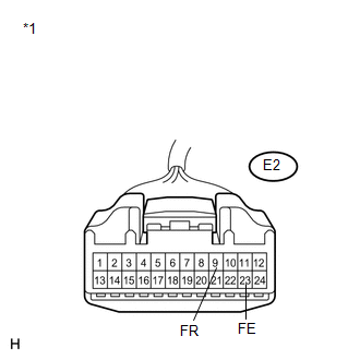
*1 |
Front view of wire harness connector (to Combination Meter Assembly) |
| OK | |
REPLACE COMBINATION METER ASSEMBLY |
|
|
3. |
CHECK HARNESS AND CONNECTOR (COMBINATION METER ASSEMBLY - FUEL SENDER GAUGE ASSEMBLY) |
(a) Disconnect the L12 connector.
(b) Measure the resistance according to the value(s) in the table below.
Standard Resistance:
|
Tester Connection |
Condition |
Specified Condition |
|---|---|---|
|
E2-9 (FR) - L12-2 |
Always |
Below 1 Ω |
|
E2-9 (FR) - Body ground |
Always |
10 kΩ or higher |
|
E2-23 (FE) - M12-2 |
Always |
Below 1 Ω |
|
E2-23 (FE) - Body ground |
Always |
10 kΩ or higher |
|
L12-3 - M12-1 |
Always |
Below 1 Ω |
|
M12-1 - Body ground |
Always |
10 kΩ or higher |
|
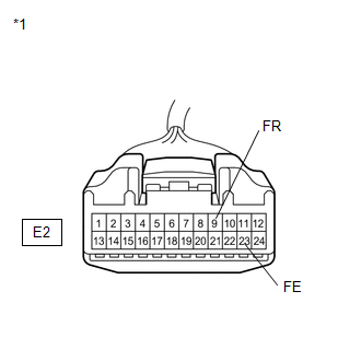
*1 |
Front view of wire harness connector (to Combination Meter Assembly) |
|
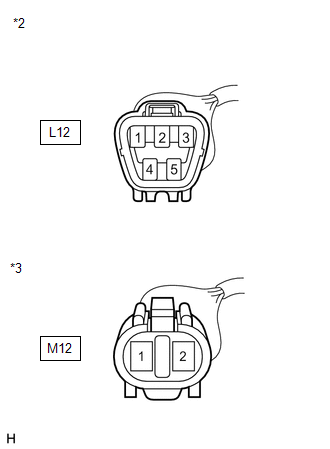
*2 |
Front view of wire harness connector (to Fuel Sender Gauge Assembly (Main)) |
|
*3 |
Front view of wire harness connector (to Fuel Sender Gauge Assembly (Sub)) |
| NG | |
REPAIR OR REPLACE HARNESS OR CONNECTOR |
|
|
4. |
INSPECT FUEL SENDER GAUGE ASSEMBLY |
(a) Remove the fuel sender gauge assembly (See page
.gif) (Main),
(Main),
(Sub)).
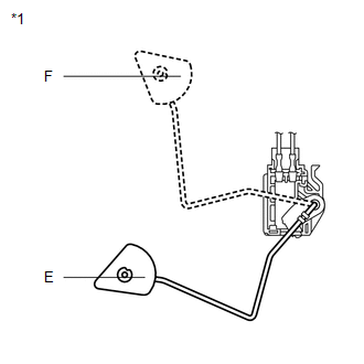
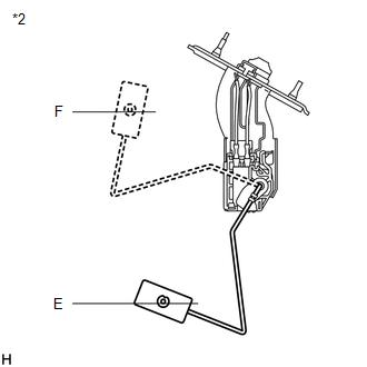
(b) Check that the float moves smoothly between E and F.
(c) Measure the resistance according to the value(s) in the table below.
Standard Resistance (Main):
|
Tester Connection |
Condition |
Specified Condition |
|---|---|---|
|
1 - 2 |
Float level is F (upper) |
6.5 to 8.5 Ω |
|
1 - 2 |
Float level is between F (upper) and E (lower) |
6.5 to 187.2 Ω (Gradually changes) |
|
1 - 2 |
Float level is E (lower) |
183.2 to 187.2 Ω |
Standard Resistance (Sub):
|
Tester Connection |
Condition |
Specified Condition |
|---|---|---|
|
1 - 2 |
Float level is F (upper) |
6.5 to 8.5 Ω |
|
1 - 2 |
Float level is between F (upper) and E (lower) |
6.5 to 227.3 Ω (Gradually changes) |
|
1 - 2 |
Float level is E (lower) |
222.3 to 227.3 Ω |
|
*1 |
Front view of wire harness connector (to Fuel Sender Gauge Assembly (Main)) |
|
*2 |
Front view of wire harness connector (to Fuel Sender Gauge Assembly (Sub)) |
|
Result |
Proceed to |
|---|---|
|
OK |
A |
|
NG (for 2GR-FE) |
B |
|
NG (for 1AR-FE) |
C |
| B | |
REPLACE FUEL SENDER GAUGE ASSEMBLY (for 2GR-FE) |
| C | |
REPLACE FUEL SENDER GAUGE ASSEMBLY (for 1AR-FE) |
|
|
5. |
CHECK FUEL SENDER GAUGE ASSEMBLY |
(a) Visually check for deformation on the fuel sender gauge assembly connector.
OK:
There is no deformation.
|
Result |
Proceed to |
|---|---|
|
OK |
A |
|
NG (for 2GR-FE) |
B |
|
NG (for 1AR-FE) |
C |
| A | |
REPLACE COMBINATION METER ASSEMBLY |
| B | |
REPLACE FUEL SENDER GAUGE ASSEMBLY (for 2GR-FE) |
| C | |
REPLACE FUEL SENDER GAUGE ASSEMBLY (for 1AR-FE) |
 On-vehicle Inspection
ON-VEHICLE INSPECTION
PROCEDURE
1. INSPECT SPEEDOMETER
(a) Check the operation.
(1) Using a speedometer tester (calibrated chassis dynamometer), check the speedometer
indication according to the ...
 Lost Communication with ECM / PCM "A" (U0100,U0129)
DESCRIPTION
The combination meter assembly communicates with the ECM via the CAN communication
system (CAN No. 1 Bus).
DTC No.
DTC Detection Condition
Trouble Area ...
Other materials about Toyota Venza:
Removal
REMOVAL
PROCEDURE
1. REMOVE ROOF DRIP CENTER SIDE FINISH MOULDING (w/o Sliding Roof)
(a) Put protective tape around the roof drip center side finish moulding.
Text in Illustration
*1
Protective Tape
...
Throttle / Pedal Position Sensor "A" Minimum Stop Performance (P2109)
DESCRIPTION
The idle speed is controlled by the Electronic Throttle Control System (ETCS).
The ETCS is comprised of a throttle actuator, which operates the throttle valve,
and a throttle position sensor, which detects the opening amount of the throttle
...
Installation
INSTALLATION
PROCEDURE
1. INSTALL DRIVE MONITOR SWITCH
(a) Engage the 4 claws to install the drive monitor switch.
2. INSTALL RADIO AND DISPLAY RECEIVER ASSEMBLY WITH BRACKET (for Radio and Display
Type)
3. INSTALL NAVIGATION RECEIVER ASSEMBLY WITH B ...

0.1145