Toyota Venza: Window Glass Antenna Wire
On-vehicle Inspection
ON-VEHICLE INSPECTION
PROCEDURE
1. INSPECT WINDOW GLASS ANTENNA WIRE
|
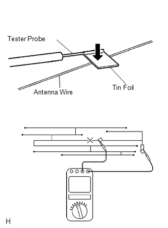
(a) Check for continuity of the antenna. HINT: Check for continuity at the center of each antenna wire as shown in the illustration. NOTICE:
OK: There is continuity in the antenna. If the result is not as specified, repair the window glass antenna wire. |
|
Repair
REPAIR
PROCEDURE
1. REPAIR WINDOW GLASS ANTENNA WIRE
(a) Clean the broken wire tips with a grease, wax and silicone remover.
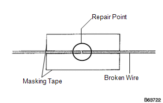
(b) Place masking tape along both sides of the wire to be repaired.
(c) Thoroughly mix the repair agent (Dupont paste No. 4817 or equivalent).
|
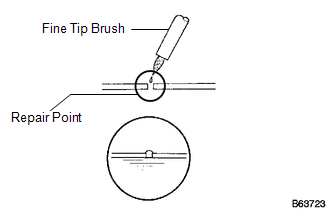
(d) Using a fine tip brush, apply a small amount of the repair agent to the wire. |
|
(e) After a few minutes, remove the masking tape.
NOTICE:
Do not repair the antenna wire again for at least 24 hours.
 Stereo Jack Adapter Assembly
Components
COMPONENTS
ILLUSTRATION
Removal
REMOVAL
PROCEDURE
1. REMOVE UPPER CONSOLE PANEL SUB-ASSEMBLY (w/o Seat Heater System)
2. REMOVE UPPER CONSOLE PANEL SUB-ASSEMBLY (w/ Seat Hea ...

Other materials about Toyota Venza:
Back Door Opener Switch
Components
COMPONENTS
ILLUSTRATION
Removal
REMOVAL
PROCEDURE
1. REMOVE BACK DOOR PANEL TRIM ASSEMBLY
2. REMOVE REAR LIGHT ASSEMBLY LH
3. REMOVE REAR LIGHT ASSEMBLY RH
HINT:
Use the same procedure for the RH side and LH side.
4. REMOVE BA ...
SFR Solenoid Circuit (C0226/21,C0236/22,C0246/23,C0256/24,C1225/25-C1228/28)
DESCRIPTION
These solenoids turn on when signals are received from the skid control ECU and
they control the pressure acting on the wheel cylinders to control the braking force.
DTC Code
DTC Detection Condition
Trouble Area ...
IG Signal Circuit
DESCRIPTION
This circuit detects the ignition switch ON or off condition, and sends it to
the main body ECU (driver side junction block assembly).
WIRING DIAGRAM
CAUTION / NOTICE / HINT
NOTICE:
Inspect the fuses for circuits related to this system b ...

0.1658