Toyota Venza: System Diagram
SYSTEM DIAGRAM
 System Description
SYSTEM DESCRIPTION
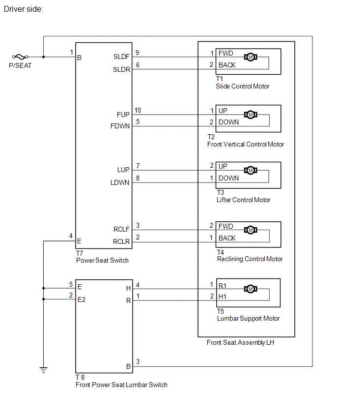
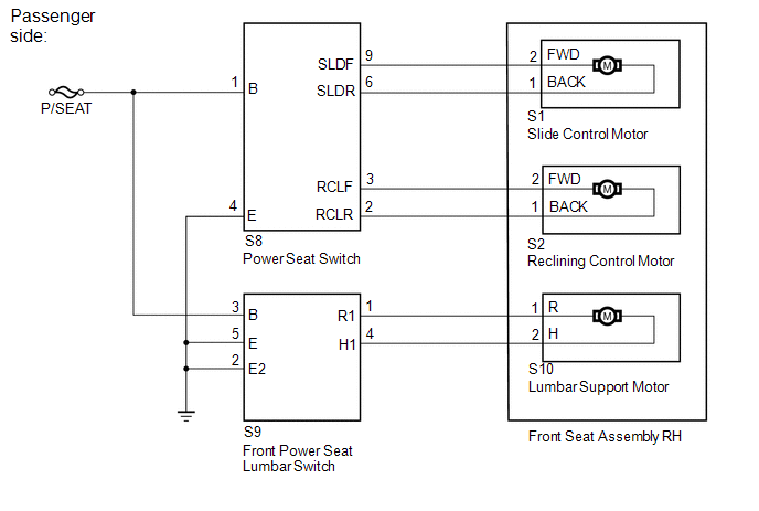
1. FRONT POWER SEAT CONTROL SYSTEM DESCRIPTION
The driver seat is equipped with slide, reclining, lifter, front vertical and
lumbar support adjustment functions.
2. FUNCTION OF ...
 Operation Check
OPERATION CHECK
1. CHECK POWER SEAT FUNCTION
(a) Check the basic functions.
(1) Operate the power seat switches and check to make sure each seat function
work:
Sliding
Front vertica ...
Other materials about Toyota Venza:
Setting up the displays
Press the “SETUP” button while the
vehicle is stopped.
The “Custom Settings” screen is displayed on the multi-information display.
If left idle for approximately 10 seconds, the display will revert to the previous
screen.
Select “Display / ...
How To Proceed With Troubleshooting
CAUTION / NOTICE / HINT
HINT:
Use the following procedure to troubleshoot the audio and visual system.
*: Use the Techstream.
PROCEDURE
1.
VEHICLE BROUGHT TO WORKSHOP
NEXT
...
Driving assist systems
To help enhance driving safety and performance, the following systems operate
automatically in response to various driving situations.
Be aware, however, that these systems are supplementary and should not be relied
upon too heavily when operating the veh ...

0.1156