Toyota Venza: Terminals Of Ecu
TERMINALS OF ECU
1. CHECK POWER BACK DOOR ECU (POWER BACK DOOR MOTOR UNIT) (w/ POWER BACK DOOR SYSTEM)
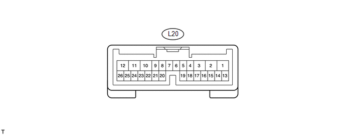
(a) Disconnect the L20 power back door ECU connector.
(b) Measure the voltage and resistance according to the value(s) in the table below.
|
Tester Connection |
Wiring Color |
Terminal Description |
Condition |
Specified Condition |
|---|---|---|---|---|
|
L20-12 (B) - Body ground |
LG - Body ground |
Battery power supply |
Always |
11 to 14 V |
|
L20-10 (ECUB) - Body ground |
P - Body ground |
Battery power supply |
Always |
11 to 14 V |
|
L20-8 (IG) - Body ground |
SB - Body ground |
IG power supply |
Ignition switch ON |
11 to 14 V |
|
L20-8 (IG) - Body ground |
SB - Body ground |
IG power supply |
Ignition switch off |
Below 1 V |
|
L20-11 (GND) - Body ground |
W-B - Body ground |
Ground |
Always |
Below 1 Ω |
If the result is not as specified, there may be a malfunction in the wire harness.
(c) Reconnect the L20 power back door ECU connector.
(d) Initialize the power back door system (See page
.gif) ).
).
(e) Measure the voltage according to the value(s) in the table below.
|
Tester Connection |
Wiring Color |
Terminal Description |
Condition |
Specified Condition |
|---|---|---|---|---|
|
L20-2 (DC+) - L20-1 (DC-) |
L - G |
Back door lock motor circuit |
Back door lock motor operating |
11 to 14 V |
|
L20-2 (DC+) - L20-1 (DC-) |
L - G |
Back door lock motor circuit |
Back door lock motor not operating |
Below 1 V |
|
L20-20 (FUL) - Body ground |
GR - Body ground |
Back door courtesy switch circuit |
Back door closed |
11 to 14 V |
|
L20-20 (FUL) - Body ground |
GR - Body ground |
Back door courtesy switch circuit |
Back door open |
Below 1 V |
|
L20-22 (HAF) - Body ground |
LG - Body ground |
Back door lock half-latch switch signal circuit |
Back door open → Back door closer operates → Back door closed |
Below 1 V → 11 to 14 V → Below 1 V |
|
L20-24 (POS) - Body ground |
P - Body ground |
Back door lock position switch signal circuit |
Back door open → Back door closer operates → Back door closed |
Below 1 V → 11 to 14 V → Below 1 V |
If the result is not as specified, the ECU may have a malfunction.
2. BACK DOOR CLOSER ECU (MULTIPLEX NETWORK DOOR ECU) (w/o POWER BACK DOOR SYSTEM)

(a) Disconnect the L21 back door closer ECU connector.
(b) Measure the voltage and resistance according to the value(s) in the table below.
|
Tester Connection |
Wiring Color |
Terminal Description |
Condition |
Specified Condition |
|---|---|---|---|---|
|
L21-4 (B) - Body ground |
LG - Body ground |
Battery power supply |
Always |
11 to 14 V |
|
L21-16 (ECUB) - Body ground |
P - Body ground |
Battery power supply |
Always |
11 to 14 V |
|
L21-15 (IG) - Body ground |
SB - Body ground |
IG power supply |
Ignition switch ON |
11 to 14 V |
|
L21-15 (IG) - Body ground |
SB - Body ground |
IG power supply |
Ignition switch off |
Below 1 V |
|
L21-3 (GND) - Body ground |
W-B - Body ground |
Ground |
Always |
Below 1 Ω |
If the result is not as specified, there may be a malfunction in the wire harness.
(c) Reconnect the L21 back door closer ECU connector.
(d) Measure the voltage according to the value(s) in the table below.
|
Tester Connection |
Wiring Color |
Terminal Description |
Condition |
Specified Condition |
|---|---|---|---|---|
|
L21-2 (DC+) - L21-1 (DC-) |
L - G |
Back door lock motor circuit |
Back door lock motor operating |
11 to 14 V |
|
L21-2 (DC+) - L21-1 (DC-) |
L - G |
Back door lock motor circuit |
Back door lock motor not operating |
Below 1 V |
|
L21-6 (FUL) - Body ground |
GR - Body ground |
Back door courtesy switch circuit |
Back door closed |
11 to 14 V |
|
L21-6 (FUL) - Body ground |
GR - Body ground |
Back door courtesy switch circuit |
Back door open |
Below 1 V |
|
L21-5 (HAF) - Body ground |
LG - Body ground |
Back door lock half-latch switch signal circuit |
Back door open → Back door closer operates → Back door closed |
Below 1 V → 11 to 14 V → Below 1 V |
|
L21-7 (POS) - Body ground |
P - Body ground |
Back door lock position switch signal circuit |
Back door open → Back door closer operates → Back door closed |
Below 1 V → 11 to 14 V → Below 1 V |
If the result is not as specified, the ECU may have a malfunction.
3. CHECK MAIN BODY ECU (DRIVER SIDE JUNCTION BLOCK ASSEMBLY)
.png)
(a) Disconnect the D49 and 2F connectors.
(b) Measure the resistance according to the value(s) in the table below.
|
Tester Connection |
Wiring Color |
Terminal Description |
Condition |
Specified Condition |
|---|---|---|---|---|
|
D49-2 (BDSU) - Body ground |
GR - Body ground |
Back door opener switch signal circuit |
Back door opener switch on |
Below 1 Ω |
|
D49-2 (BDSU) - Body ground |
GR - Body ground |
Back door opener switch signal circuit |
Back door opener switch off |
10 kΩ or higher |
|
2F-16 (GND1) - Body ground |
W-B - Body ground |
Ground |
Always |
Below 1 Ω |
If the result is not as specified, there may be a malfunction on the wire harness side.
(c) Reconnect the D49 and 2F connectors.
(d) Measure the voltage according to the value(s) in the table below.
|
Tester Connection |
Wiring Color |
Terminal Description |
Condition |
Specified Condition |
|---|---|---|---|---|
|
D49-2 (BDSU) - Body ground |
GR - Body ground |
Back door opener switch signal circuit |
Back door opener switch off |
Pulse generation |
|
D49-2 (BDSU) - Body ground |
GR - Body ground |
Back door opener switch signal circuit |
Back door opener switch on |
Below 1 V |
If the result is not as specified, the ECU may have a malfunction.
 Problem Symptoms Table
PROBLEM SYMPTOMS TABLE
HINT:
Use the table below to help determine the cause of problem symptoms.
If multiple suspected areas are listed, the potential causes of the symptoms
are lis ...
 Diagnosis System
DIAGNOSIS SYSTEM
1. DESCRIPTION
(a) The power back door ECU (power back door motor unit)*1 or back door closer
ECU (multiplex network door ECU)*2 controls the vehicle's back door closer system ...
Other materials about Toyota Venza:
Inspection
INSPECTION
PROCEDURE
1. INSPECT BRAKE DISC INSIDE DIAMETER
(a) Using a brake drum gauge or an equivalent tool, measure the inside
diameter of the disc.
Standard inside diameter of a new disc:
190 mm (7.48 in.)
Maximum inside diamete ...
Installation
INSTALLATION
CAUTION / NOTICE / HINT
HINT:
Use the same procedure for the RH side and LH side.
The procedure listed below is for the LH side.
PROCEDURE
1. INSTALL FRONT AIRBAG SENSOR
(a) Check that the ignition switch is off.
(b) Check ...
MIL Circuit
DESCRIPTION
The MIL (Malfunction Indicator Lamp) is used to indicate vehicle malfunctions
detected by the ECM. By turning the ignition switch to ON, power is supplied to
the MIL circuit, and the ECM provides the circuit ground which illuminates the MIL.
...

0.1536