Toyota Venza: Electrical Key Oscillator(for Rear Side)
Components
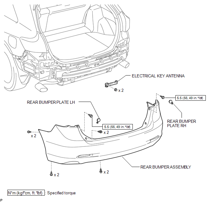
COMPONENTS
ILLUSTRATION
Removal
REMOVAL
PROCEDURE
1. REMOVE REAR BUMPER PLATE LH
.gif)
2. REMOVE REAR BUMPER PLATE RH
3. REMOVE REAR BUMPER ASSEMBLY
4. REMOVE ELECTRICAL KEY ANTENNA
|
(a) Disconnect the connector. |
|
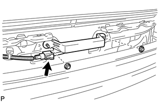
(b) Remove the 2 nuts and the electrical key antenna.
NOTICE:
Be careful when removing the electrical key antenna. If the antenna is dropped, replace it with a new one.
Installation
INSTALLATION
PROCEDURE
1. INSTALL ELECTRICAL KEY ANTENNA
|
(a) Install the electrical key antenna with the 2 nuts. NOTICE: Be careful when installing the electrical key antenna. If the antenna is dropped, replace it with a new one. |
|
.png)
(b) Connect the connector.
2. INSTALL REAR BUMPER ASSEMBLY
.gif)
3. INSTALL REAR BUMPER PLATE LH
4. INSTALL REAR BUMPER PLATE RH
 Electrical Key Oscillator(for Rear Floor)
Components
COMPONENTS
ILLUSTRATION
Removal
REMOVAL
PROCEDURE
1. REMOVE TONNEAU COVER ASSEMBLY (w/ Tonneau Cover)
2. REMOVE DECK BOARD ASSEMBLY
3. REMOVE NO. 3 DECK BOARD SUB-ASSEMB ...
 Engine Hood Courtesy Switch
Components
COMPONENTS
ILLUSTRATION
Inspection
INSPECTION
PROCEDURE
1. INSPECT SECURITY COURTESY SWITCH (HOOD LOCK ASSEMBLY)
(a) Measure the resistance according to the value(s) ...
Other materials about Toyota Venza:
Precaution
PRECAUTION
1. EXPRESSIONS OF IGNITION SWITCH
(a) The type of ignition switch used on this model differs according to the specifications
of the vehicle. The expressions listed in the table below are used in this section.
Switch Type
I ...
Unlocking and locking the doors
►Front door handle
Grip the driver’s door handle to unlock the door. Grip the passenger’s door handle
to unlock all the doors.* Make sure to touch the sensor on the back of the handle.
The doors cannot be unlocked for 3 seconds after the doors ...
Diagnostic Trouble Code Chart
DIAGNOSTIC TROUBLE CODE CHART
Navigation System
DTC Code
Detection Item
See page
B1532
LVDS Signal Malfunction (from Extension Module)
B1551
HD Radio Tuner ...

0.168