Toyota Venza: Inspection
INSPECTION
PROCEDURE
1. INSPECT SPIRAL CABLE
(a) Visually check for defects with the spiral cable removed from the vehicle.
(1) The defects are as follows:
- Scratches on the spiral cable
- Small cracks the spiral cable
- Dents on the spiral cable
- Chips on the spiral cable
- Cracks or other damage to the connector
OK:
No defects are found.
HINT:
If any of the defects is found, replace the spiral cable with a new one.
|
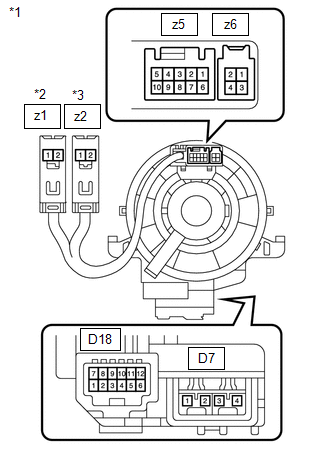
(b) Inspect the spiral cable. Text in Illustration
(1) Measure the resistance according to the value(s) in the table below. NOTICE: To avoid breakage of the spiral cable, do not turn the spiral cable more than necessary. If the value is not within the specified range, replace the spiral cable. Standard Resistance
|
|
 Components
COMPONENTS
ILLUSTRATION
...
 Removal
REMOVAL
PROCEDURE
1. PRECAUTION
CAUTION:
Be sure to read Precaution thoroughly before servicing (See page
).
2. TURN FRONT WHEELS TO FACE STRAIGHT AHEAD
3. DISCONNECT CABLE FROM NEGATIVE BATTE ...
Other materials about Toyota Venza:
Freeze Frame Data
FREEZE FRAME DATA
1. CHECK FREEZE FRAME DATA
(a) Connect the Techstream to the DLC3.
(b) Turn the ignition switch to ON.
(c) Turn the Techstream on.
(d) Enter the following menus: Body Electrical / Navigation System / Trouble
Codes.
(e) Select a DTC to ...
Check CAN Bus Lines for Short Circuit
DESCRIPTION
There may be a short circuit in the CAN bus main wire and/or CAN branch wire
when the resistance between terminals 6 (CANH) and 14 (CANL) of the DLC3 is below
54 Ω.
Symptom
Trouble Area
Resistance betwe ...
Security Indicator Light Circuit
DESCRIPTION
Even when the theft deterrent system is in the disarmed state, the security indicator
blinks due to a signal output from the immobiliser system. The security indicator
blinks continuously due to a continuous signal received from the immobilise ...

0.1183