Toyota Venza: Front Blower Motor
Components
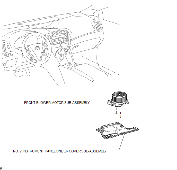
COMPONENTS
ILLUSTRATION
Installation
INSTALLATION
PROCEDURE
1. INSTALL FRONT BLOWER MOTOR SUB-ASSEMBLY
|
(a) Install the front blower motor sub-assembly with the 3 screws. |
|
(b) Connect the connector.
2. INSTALL NO. 2 INSTRUMENT PANEL UNDER COVER SUB-ASSEMBLY
.gif)
3. CONNECT CABLE TO NEGATIVE BATTERY TERMINAL
NOTICE:
When disconnecting the cable, some systems need to be initialized after the cable
is reconnected (See page ).
Removal
REMOVAL
PROCEDURE
1. DISCONNECT CABLE FROM NEGATIVE BATTERY TERMINAL
NOTICE:
When disconnecting the cable, some systems need to be initialized after the cable
is reconnected (See page .gif) ).
).
2. REMOVE NO. 2 INSTRUMENT PANEL UNDER COVER SUB-ASSEMBLY
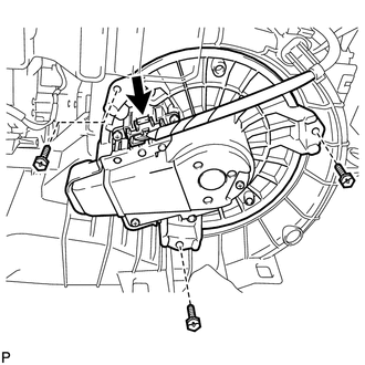
3. REMOVE FRONT BLOWER MOTOR SUB-ASSEMBLY
|
(a) Disconnect the connector. |
|
.png)
(b) Remove the 3 screws and front blower motor sub-assembly.
 Reassembly
REASSEMBLY
PROCEDURE
1. INSTALL COOLER DRYER
(a) Using pliers, install a new cooler dryer to the modulator.
(b) Apply sufficien ...

Other materials about Toyota Venza:
Steering Lock Motor Drive Power Circuit
DESCRIPTION
The steering lock ECU (steering lock actuator assembly) is connected to the power
management control ECU. The steering lock ECU (steering lock actuator assembly)
cannot activate the motor unless it receives permission signals from both ECUs.
...
Components
COMPONENTS
ILLUSTRATION
ILLUSTRATION
ILLUSTRATION
ILLUSTRATION
ILLUSTRATION
...
VSC OFF Indicator Light Remains ON
DESCRIPTION
The skid control ECU is connected to the combination meter via CAN communication.
Pressing the VSC OFF switch turns off traction control and pressing and holding
this switch turns off traction and VSC controls. If VSC control is turned off, the ...

0.1753