Toyota Venza: Parts Location
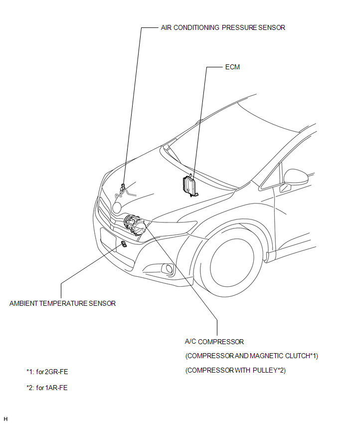
PARTS LOCATION
ILLUSTRATION
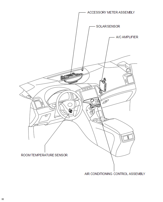
ILLUSTRATION
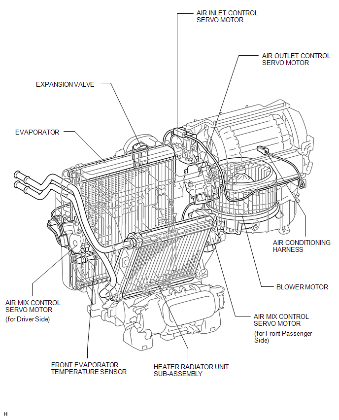
ILLUSTRATION
 Precaution
PRECAUTION
NOTICE:
When disconnecting the cable from the negative (-) battery terminal, initialize
the following systems after the cable is reconnected.
System Name
See Proc ...
 System Diagram
SYSTEM DIAGRAM
Communication Table
Sender
Receiver
Signal
Communication Line
A/C amplifier
ECM
Magnetic clutch req ...
Other materials about Toyota Venza:
A/C ECU Vehicle Information Reading/Writing Processor Malfunction (B15F5)
DESCRIPTION
This DTC is stored when items controlled by the air conditioning amplifier assembly
cannot be customized via the audio and visual system vehicle customization screen.
HINT:
The air conditioning amplifier assembly controls the air conditioning ...
Initialization
INITIALIZATION
1. RESET TRANSAXLE COMPENSATION CODE
NOTICE:
If the following parts have been replaced, initialize the TCM and perform
the following "Reset Memory" and "Perform Road Test to Allow TCM to learn"
steps.
- ...
System Diagram
SYSTEM DIAGRAM
Communication Table
Transmitting ECU
Receiving ECU
Signal
Communication Method
Air Conditioning Control Assembly
Air Conditioning Amplifier Assembly
Rear windo ...

0.1305