Toyota Venza: System Diagram
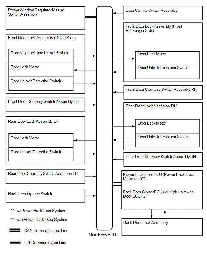
SYSTEM DIAGRAM
 Parts Location
PARTS LOCATION
ILLUSTRATION
ILLUSTRATION
...
 System Description
SYSTEM DESCRIPTION
1. POWER DOOR LOCK CONTROL SYSTEM DESCRIPTION
(a) The power door lock system locks/unlocks all doors.
The door control switch sends "lock/unlock" request signals to the ...
Other materials about Toyota Venza:
Removal
REMOVAL
PROCEDURE
1. PRECAUTION
CAUTION:
Be sure to read Precaution thoroughly before servicing (See page
).
If the front seat side airbag assembly was deployed, replace the front
seat side airbag assembly, front seat frame assembly wit ...
Radio Broadcast cannot be Received or Poor Reception
PROCEDURE
1.
CHECK NAVIGATION RECEIVER ASSEMBLY
(a) Check the radio automatic station search function.
(1) Check the radio automatic station search function by activating it.
Result
Proceed to
...
Disassembly
DISASSEMBLY
PROCEDURE
1. REMOVE NO. 1 SIDE DEFROSTER NOZZLE DUCT
(a) Remove the 2 screws <E> or <F> and remove the No. 1 side defroster
nozzle duct.
2. REMOVE NO. 2 SIDE DEFROSTER NO ...

0.1142