Toyota Venza: Parts Location
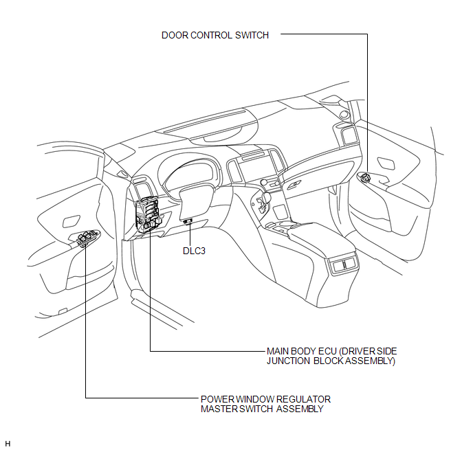
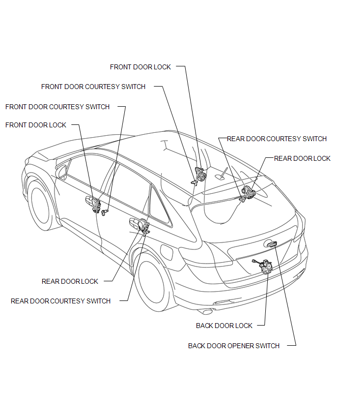
PARTS LOCATION
ILLUSTRATION
ILLUSTRATION
 Precaution
PRECAUTION
NOTICE:
When disconnecting the cable from the negative (-) battery terminal, initialize
the following systems after the cable is reconnected.
System Name
See Proc ...
 System Diagram
SYSTEM DIAGRAM
...
Other materials about Toyota Venza:
Mechanical System Tests
MECHANICAL SYSTEM TESTS
1. STALL SPEED TEST
HINT:
This test is to check the overall performance of the engine and transaxle.
CAUTION:
Driving test should be done on a paved surface (a surface that is not
slippery).
To ensure safety, perfor ...
Satellite Radio Antenna
Components
COMPONENTS
ILLUSTRATION
ILLUSTRATION
Removal
REMOVAL
PROCEDURE
1. REMOVE ROOF HEADLINING ASSEMBLY
(See page )
2. REMOVE ROOF ANTENNA POLE SUB-ASSEMBLY
3. REMOVE SATELLITE RADIO ANTENNA ASSEMBLY
(a) Disconnect the co ...
Initialization has not been Performed (B2450)
DESCRIPTION
The headlight leveling ECU assembly stores this DTC if initialization has not
been performed after the ECU was replaced.
DTC No.
DTC Detecting Condition
Trouble Area
B2450
Initializat ...

0.1698