Toyota Venza: System Diagram
SYSTEM DIAGRAM
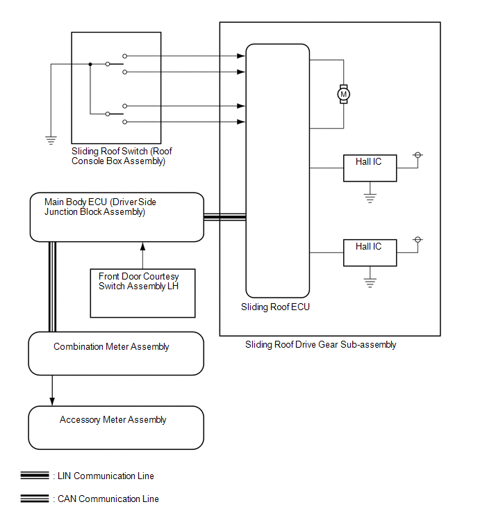 Communication Table
|
Sender |
Receiver |
Signal |
Line |
|---|---|---|---|
|
Main body ECU (Driver side junction block assembly) |
Sliding roof ECU (Sliding roof drive gear sub-assembly) |
Key off operation signal |
LIN |
|
Main body ECU (Driver side junction block assembly) |
Combination meter assembly |
Sliding roof open warning signal |
CAN |
 Parts Location
PARTS LOCATION
ILLUSTRATION
...
 System Description
SYSTEM DESCRIPTION
1. GENERAL
This system has the following functions: manual slide open and close; auto slide
open; manual tilt up and down; auto tilt up; jam protection; key off operation.
2. F ...
Other materials about Toyota Venza:
Pressure Control Solenoid "G" Electrical (Shift Solenoid Valve SL4) (P2810)
DESCRIPTION
Changing from 1st to 6th is performed by the TCM turning shift solenoid valves
SL1, SL2, SL3, SL4 and SL on and off. If an open or short circuit occurs in any
of the shift solenoid valves, the TCM controls the remaining normal shift solenoid
...
Precaution
PRECAUTION
NOTICE:
When disconnecting the cable from the negative (-) battery terminal, initialize
the following systems after the cable is reconnected.
System Name
See Procedure
Back Door Closer System
...
Washer Motor(for Rear Side)
Components
COMPONENTS
ILLUSTRATION
Removal
REMOVAL
PROCEDURE
1. REMOVE FRONT WHEEL RH
2. REMOVE FRONT FENDER OUTSIDE MOULDING RH
HINT:
Use the same procedure for the RH side and LH side (See page
).
3. REMOVE FRONT FENDER LINER RH
4. DRAI ...

0.1216