Toyota Venza: Components
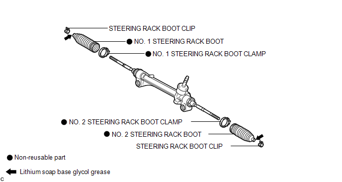
COMPONENTS
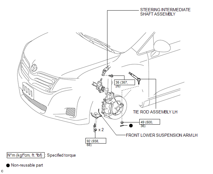
ILLUSTRATION
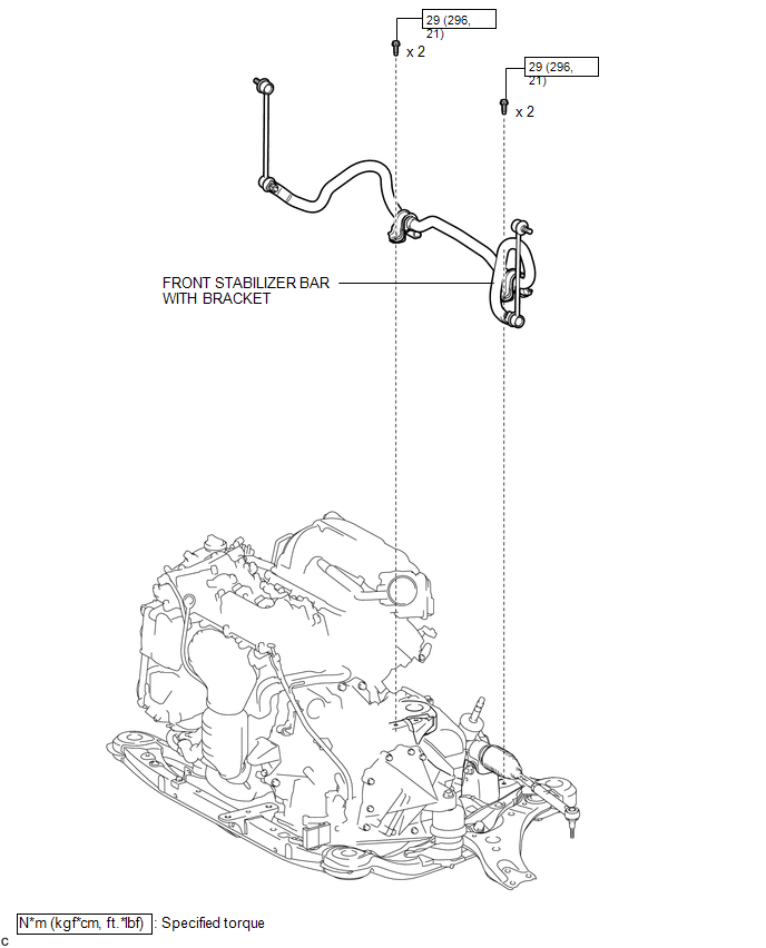
ILLUSTRATION
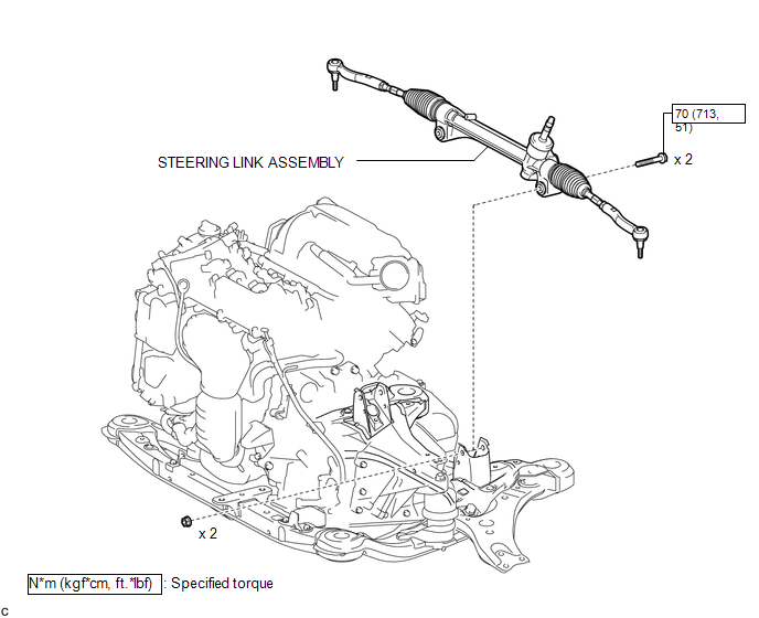
ILLUSTRATION
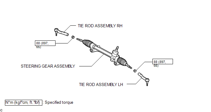
ILLUSTRATION
ILLUSTRATION

 Removal
REMOVAL
CAUTION / NOTICE / HINT
NOTICE:
When disconnecting the steering intermediate shaft assembly and pinion shaft
of steering gear assembly, be sure to place matchmarks before servicing.
PROC ...
Other materials about Toyota Venza:
Test Mode Procedure
TEST MODE PROCEDURE
1. DESCRIPTION
HINT:
When using a chassis dynamometer, brake tester, etc. to perform a vehicle test,
activate test mode to avoid a "different tire diameter installed" incorrect judgment.
Test mode does not have a AWD paramet ...
Problem Symptoms Table
PROBLEM SYMPTOMS TABLE
HINT:
Use the table below to help determine the cause of problem symptoms.
If multiple suspected areas are listed, the potential causes of the symptoms
are listed in order of probability in the "Suspected Area" ...
Occupant Classification Sensor Power Supply Circuit Malfunction (B1793)
DESCRIPTION
The occupant classification sensor power supply circuit consists of the occupant
classification ECU and occupant classification sensors.
DTC B1793 is recorded when a malfunction is detected in the occupant classification
sensor power supply c ...

0.1207