Toyota Venza: Power Back Door Control Switch
Components
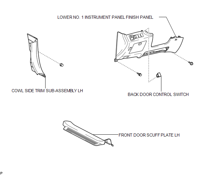
COMPONENTS
ILLUSTRATION
Inspection
INSPECTION
PROCEDURE
1. INSPECT POWER BACK DOOR OPENER / CLOSER SWITCH
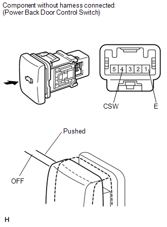
(a) Measure the resistance of the switch.
Standard resistance:
|
Tester Connection |
Condition |
Specified Condition |
|---|---|---|
|
1(E) - 4(CSW) |
Pushed (ON) |
Below 1 Ω |
|
1(E) - 4(CSW) |
Free (OFF) |
10 kΩ or higher |
If the result is not as specified, replace the switch.
(b) Check that the switch illuminates.
Standard resistance:
|
Measurement Condition |
Specified Condition |
|---|---|
|
Battery positive (+) → 3 (ILL+) Battery negative (-) → 2 (ILL-) |
Illuminates |
If the result is not as specified, replace the switch.
Removal
REMOVAL
PROCEDURE
1. REMOVE FRONT DOOR SCUFF PLATE LH
.gif)
2. REMOVE COWL SIDE TRIM SUB-ASSEMBLY LH
3. REMOVE LOWER NO. 1 INSTRUMENT PANEL FINISH PANEL
4. REMOVE BACK DOOR CONTROL SWITCH
|
(a) Disengage the 2 claws and remove the back door control switch. |
|
Installation
INSTALLATION
PROCEDURE
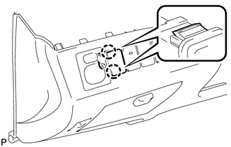
1. INSTALL BACK DOOR CONTROL SWITCH
|
(a) Engage the 2 claws to install the back door control switch. |
|
.png)
2. INSTALL LOWER NO. 1 INSTRUMENT PANEL FINISH PANEL
.gif)
3. INSTALL COWL SIDE TRIM SUB-ASSEMBLY LH
4. INSTALL FRONT DOOR SCUFF PLATE LH
 Power Back Door Closer Switch
Components
COMPONENTS
ILLUSTRATION
Removal
REMOVAL
PROCEDURE
1. REMOVE BACK DOOR PANEL TRIM ASSEMBLY
2. REMOVE POWER BACK DOOR CLOSER SWITCH ASSEMBLY
(a) Disconnect the con ...

Other materials about Toyota Venza:
Removal
REMOVAL
CAUTION / NOTICE / HINT
HINT:
The front side fix window assembly can be reused. When installing the
window, if any of the clips on the front side fix window assembly are broken,
butyl tape can be used to support the glass until the a ...
Diagnostic Trouble Code Chart
DIAGNOSTIC TROUBLE CODE CHART
HINT:
If a trouble code is stored during the DTC check, inspect the trouble areas listed
for that code. For details of the code, refer to the "See page" below.
1. CERTIFICATION ECU (SMART KEY ECU ASSEMBLY) DIAGNOSTI ...
Diagnosis System
DIAGNOSIS SYSTEM
1. DESCRIPTION
(a) The power back door ECU (power back door motor unit) controls the power back
door system functions. Power back door system data and Diagnostic Trouble Code (DTC)
can be read through the Data Link Connector 3 (DLC3).
W ...

0.1766