Toyota Venza: System Diagram
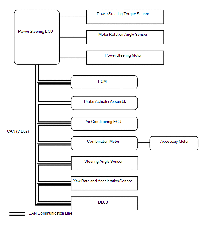
SYSTEM DIAGRAM
|
Transmitting ECU (Transmitter) |
Receiving ECU |
Signal |
Communication Method |
|---|---|---|---|
|
ECM |
Power Steering ECU |
|
CAN |
|
Brake Actuator Assembly (Skid Control ECU) |
Power Steering ECU |
|
CAN |
|
Steering Angle Sensor |
Power Steering ECU |
|
CAN |
|
Yaw Rate Sensor and Acceleration Sensor |
Power Steering ECU |
|
CAN |
|
Power Steering ECU |
ECM |
EPS idle up request signal |
CAN |
|
Power Steering ECU |
Air Conditioning ECU |
Loading control level signal |
CAN |
|
Power Steering ECU |
Combination Meter |
|
CAN |
|
Power Steering ECU |
Brake Actuator Assembly (Skid Control ECU) |
|
CAN |
 Precaution
PRECAUTION
1. PRECAUTION FOR DISCONNECTING THE BATTERY CABLE
NOTICE:
When disconnecting the cable from the negative (-) battery terminal, initialize
the following systems after the cable is recon ...
 How To Proceed With Troubleshooting
CAUTION / NOTICE / HINT
HINT:
Use the following procedure to troubleshoot the power steering system.
*: Use the Techstream.
PROCEDURE
1.
VEHICLE BROUGHT ...
Other materials about Toyota Venza:
Terminals Of Ecu
TERMINALS OF ECU
1. CHECK CERTIFICATION ECU (SMART KEY ECU ASSEMBLY)
(a) Disconnect the D25 certification ECU (smart key ECU assembly) connector.
(b) Measure the voltage and resistance according to the value(s) in the table
below.
HINT:
Measure the va ...
Side doors
The vehicle can be locked and unlocked using the entry function, wireless
remote control, key or door lock switch.
- Entry function (vehicles with smart key system)
- Wireless remote control
- Key
► Vehicles with smart key system ...
Electronic Circuit Inspection Procedure
ELECTRONIC CIRCUIT INSPECTION PROCEDURE
1. BASIC INSPECTION
(a) WHEN MEASURING RESISTANCE OF ELECTRONIC PARTS
(1) Unless otherwise stated, all resistance measurements are standard values
measured at an ambient temperature of 20°C (68°F). Resistance meas ...

0.1296